Brother International HL-720 Service Manual - Page 24
Program ROM, Working S-RAM
 |
View all Brother International HL-720 manuals
Add to My Manuals
Save this manual to your list of manuals |
Page 24 highlights
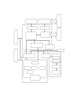
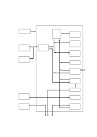
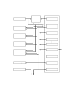
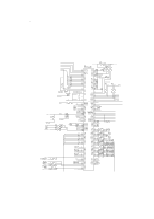
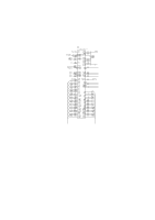
1.3.2 ASIC The ASIC is composed of Cell Based IC and has the following function blocks. (1) Oscillator circuit Oscillator circuit drives the outside ceramic resonator, and generates the main clock for the CPU core by dividing the source clock frequency into two. It is also equipped with the several clocks for timer unit, engine control I/O unit, CDCC parallel I/O unit, data extension unit and FIFO. (2) Program ROM The program ROM of 16 Kbytes is contained in this ASIC. (3) Working S-RAM The working S-RAM of 512 Bytes is also contained in this ASIC as a work RAM for the CPU core. (4) DRAM control circuit This circuit generates the RAS, CAS, WE, OE and MA signals for the DRAM and controls the refresh for the DRAM (CAS before RAS self-refreshing method). The CPU core, the CDCC parallel I/O unit and the data extension unit access the DRAM through the DRAM bus controlled by the DRAM control unit. (5) Interrupt control This circuit controls all the interrupts to the CPU core. The CPU core has no priority to each interrupt element. If the first interrupt is accepted, then the second waits until the first has been complete. The interrupt elements can be masked respectively. (6) Timers The following timers are incorporated: Timer 1 16-bit timer Timer 2 10-bit timer Timer 3 Watch-dog timer II-7
-
 1
1 -
2
-
3
-
4
-
5
-
6
-
7
-
8
-
9
-
10
-
11
-
12
-
13
-
14
-
15
-
16
-
17
-
18
-
 19
19 -
 20
20 -
 21
21 -
 22
22 -
 23
23 -
 24
24 -
 25
25 -
 26
26 -
 27
27 -
 28
28 -
 29
29 -
30
-
31
-
32
-
33
-
34
-
35
-
36
-
37
-
38
-
39
-
40
-
41
-
42
-
43
-
44
-
45
-
46
-
47
-
48
-
49
-
50
-
51
-
52
-
53
-
54
-
55
-
56
-
57
-
58
-
59
-
60
-
61
-
62
-
63
-
64
-
65
-
66
-
67
-
68
-
69
-
70
-
71
-
72
-
73
-
74
-
75
-
76
-
77
-
78
-
79
-
80
-
81
-
82
-
83
-
84
-
85
-
86
-
87
-
88
-
89
-
90
-
91
-
92
-
93
-
94
-
95
-
96
-
97
-
98
-
99
-
100
-
101
-
102
-
103
-
104
-
105
-
106
-
107
-
108
-
109
-
110
-
111
-
112
-
113
-
114
-
115
-
116
-
117
-
118
-
119
-
120
-
121
-
122
-
123
-
124
-
125
-
126
-
127
-
128
-
129
-
130
-
131
-
132
-
133
-
134
-
135
-
136
-
137
-
138
-
139
-
140
-
141
-
142
-
143
-
144
-
145
-
146
-
147
-
148
-
149
-
150
-
151
-
152
-
153
-
154
 |
 |