Brother International HL-720 Service Manual - Page 120
Lifting up the fixing unit, disconnect the two heater harnesses and disconnect
 |
View all Brother International HL-720 manuals
Add to My Manuals
Save this manual to your list of manuals |
Page 120 highlights
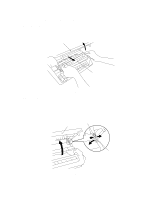
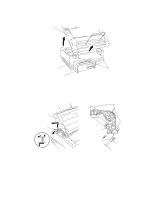
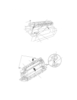
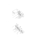
PR98292 3.4 Fixing Unit (1) Remove the M4x12 screw securing the fixing unit. (2) Lifting up the fixing unit, disconnect the two heater harnesses and disconnect the thermistor cable from the connector on the EL PCB. Fixing unit Taptite, M4x12 Heater harness (Blue) Heater harness (Brown) Thermistor harness (White) EL PCB Fig. 3.5 (3) Remove the two M3x10 screws. (4) Open the fixing unit cover along the open side of the fixing unit cover. Fixing unit cover Taptite, M3x10 Fixing unit cover Pressure roller Shaft Fixing unit frame Fig. 3.5a III-5
-
 1
1 -
2
-
3
-
4
-
5
-
6
-
7
-
8
-
9
-
10
-
11
-
12
-
13
-
14
-
15
-
16
-
17
-
18
-
19
-
20
-
21
-
22
-
23
-
24
-
25
-
26
-
27
-
28
-
29
-
30
-
31
-
32
-
33
-
34
-
35
-
36
-
37
-
38
-
39
-
40
-
41
-
42
-
43
-
44
-
45
-
46
-
47
-
48
-
49
-
50
-
51
-
52
-
53
-
54
-
55
-
56
-
57
-
58
-
59
-
60
-
61
-
62
-
63
-
64
-
65
-
66
-
67
-
68
-
69
-
70
-
71
-
72
-
73
-
74
-
75
-
76
-
77
-
78
-
79
-
80
-
81
-
82
-
83
-
84
-
85
-
86
-
87
-
88
-
89
-
90
-
91
-
92
-
93
-
94
-
95
-
96
-
97
-
98
-
99
-
100
-
101
-
102
-
103
-
104
-
105
-
106
-
107
-
108
-
109
-
110
-
111
-
112
-
113
-
114
-
 115
115 -
 116
116 -
 117
117 -
 118
118 -
 119
119 -
 120
120 -
 121
121 -
 122
122 -
 123
123 -
 124
124 -
 125
125 -
126
-
127
-
128
-
129
-
130
-
131
-
132
-
133
-
134
-
135
-
136
-
137
-
138
-
139
-
140
-
141
-
142
-
143
-
144
-
145
-
146
-
147
-
148
-
149
-
150
-
151
-
152
-
153
-
154
 |
 |

III-5
3.4
Fixing Unit
(1)
Remove the
M4x12 screw securing the fixing unit.
(2)
Lifting up the fixing unit, disconnect the two heater harnesses and disconnect the
thermistor cable from the connector on the EL PCB.
Fig. 3.5
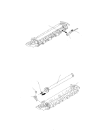
(3)
Remove the two M3x10 screws.
(4)
Open the fixing unit cover along the open side of the fixing unit cover.
Fig. 3.5a
Fixing unit
Heater harness (Blue)
Thermistor harness (White)
Heater harness (Brown)
EL PCB
Taptite, M4x12
Fixing unit
cover
Shaft
Fixing unit cover
Pressure
roller
Fixing unit frame
PR98292
Taptite, M3x10