Brother International HL-720 Service Manual - Page 123
Base Plate Assy, Fig. 3.8, Panel sensor, PCB Assy, Prior to turning the printer upside-down
 |
View all Brother International HL-720 manuals
Add to My Manuals
Save this manual to your list of manuals |
Page 123 highlights
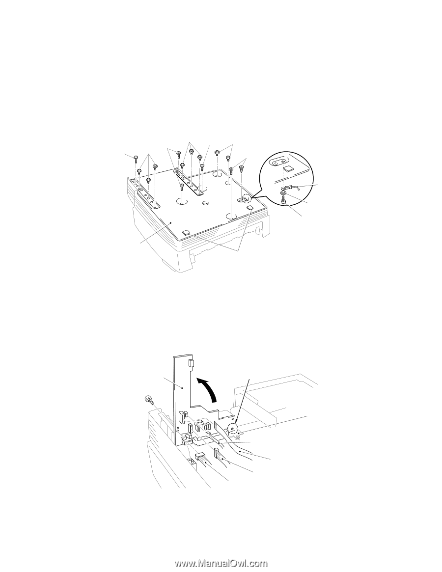
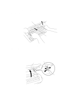
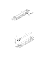
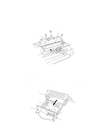
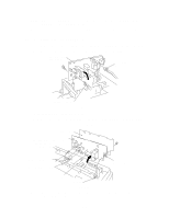
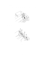
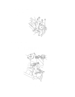
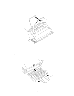
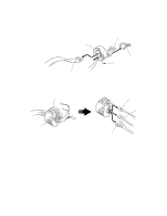
3.7 Base Plate Assy NOTE: Prior to turning the printer upside-down, the drum unit should be removed from the printer. (1) Turn the printer upside down. (2) Remove the six M4 and eight M3 tapping screws. (3) Lift out the base plate assy and remove the grounding screw. M3 Screws M4 Screws (B tight) (S tight) M4 Screws (B tight) M3 Screws (S tight) M3 Screws (S tight) M4 Screws (B tight) M4 Screws (B tight) Grounding wire Washer Grounding screw Base plate assy Rubber foot Fig. 3.8 3.8 Panel sensor PCB Assy (1) Remove the screw securing the panel sensor PCB assy. Slide the part A from under the main shield and lift the PCB assembly upwards. (2) Disconnect the seven connectors from the PCB (The three connectors P2, P3 and P9 have already disconnected when disassembling the scanner unit. See page, III5). A Panel sensor PCB assy Main Shield Solenoid harness (P6) HV flat cable (P7) LV harness (P4) Main (feed) motor harness (P5) Fig. 3.9 III-8
-
 1
1 -
2
-
3
-
4
-
5
-
6
-
7
-
8
-
9
-
10
-
11
-
12
-
13
-
14
-
15
-
16
-
17
-
18
-
19
-
20
-
21
-
22
-
23
-
24
-
25
-
26
-
27
-
28
-
29
-
30
-
31
-
32
-
33
-
34
-
35
-
36
-
37
-
38
-
39
-
40
-
41
-
42
-
43
-
44
-
45
-
46
-
47
-
48
-
49
-
50
-
51
-
52
-
53
-
54
-
55
-
56
-
57
-
58
-
59
-
60
-
61
-
62
-
63
-
64
-
65
-
66
-
67
-
68
-
69
-
70
-
71
-
72
-
73
-
74
-
75
-
76
-
77
-
78
-
79
-
80
-
81
-
82
-
83
-
84
-
85
-
86
-
87
-
88
-
89
-
90
-
91
-
92
-
93
-
94
-
95
-
96
-
97
-
98
-
99
-
100
-
101
-
102
-
103
-
104
-
105
-
106
-
107
-
108
-
109
-
110
-
111
-
112
-
113
-
114
-
115
-
116
-
117
-
 118
118 -
 119
119 -
 120
120 -
 121
121 -
 122
122 -
 123
123 -
 124
124 -
 125
125 -
 126
126 -
 127
127 -
 128
128 -
129
-
130
-
131
-
132
-
133
-
134
-
135
-
136
-
137
-
138
-
139
-
140
-
141
-
142
-
143
-
144
-
145
-
146
-
147
-
148
-
149
-
150
-
151
-
152
-
153
-
154
 |
 |