Brother International HL-720 Service Manual - Page 28
CPU Receiving Mode, This supports the IEEE1284 data transfer with the following mode.
 |
View all Brother International HL-720 manuals
Add to My Manuals
Save this manual to your list of manuals |
Page 28 highlights
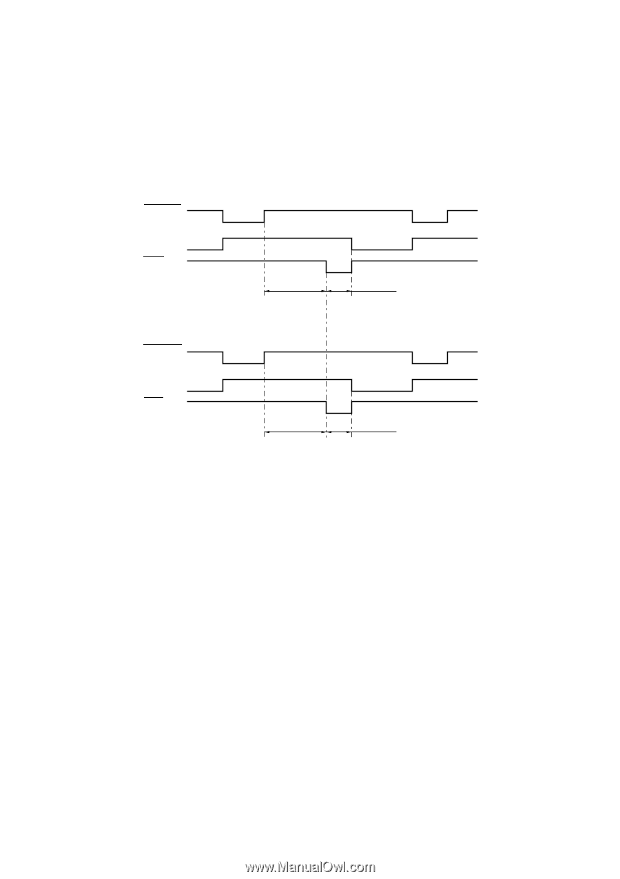
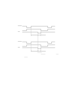
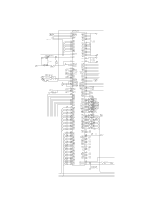
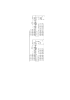
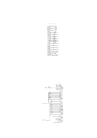
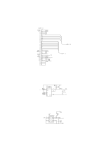
(7) CDCC parallel I/O There are two modes in this unit. One is the CPU receiving mode and the other is the DMA receiving mode. In the CPU receiving mode the CPU receives the command data from the PC, and after the CPU is switched to the DMA mode, it receives the image data and writes to the DRAM directly. CPU Receiving Mode STROBE BUSY ACK 90 µsec 0.5 µsec STROBE BUSY ACK 1.5 µsec 0.5 µsec BUSY goes HIGH at the falling edge of STROBE. The data (8 bits) from the PC is latched in the data buffer at the rising edge of STROBE. The pulse width of ACK differs according to the speed MODE as shown above. BUSY goes LOW at the rising edge of ACK. This supports the IEEE1284 data transfer with the following mode. Nibble mode Byte mode (8) Data extension This circuit extents the compressed image data which are received from the PC, and writes the bit map data to the FIFO. (9) Software support Supports 16 x 16 rotation, bit expansion, and bit search. (10)EEPROM I/O One output port and one I/O port are assigned. II-11
-
 1
1 -
2
-
3
-
4
-
5
-
6
-
7
-
8
-
9
-
10
-
11
-
12
-
13
-
14
-
15
-
16
-
17
-
18
-
19
-
20
-
21
-
22
-
 23
23 -
 24
24 -
 25
25 -
 26
26 -
 27
27 -
 28
28 -
 29
29 -
 30
30 -
 31
31 -
 32
32 -
 33
33 -
34
-
35
-
36
-
37
-
38
-
39
-
40
-
41
-
42
-
43
-
44
-
45
-
46
-
47
-
48
-
49
-
50
-
51
-
52
-
53
-
54
-
55
-
56
-
57
-
58
-
59
-
60
-
61
-
62
-
63
-
64
-
65
-
66
-
67
-
68
-
69
-
70
-
71
-
72
-
73
-
74
-
75
-
76
-
77
-
78
-
79
-
80
-
81
-
82
-
83
-
84
-
85
-
86
-
87
-
88
-
89
-
90
-
91
-
92
-
93
-
94
-
95
-
96
-
97
-
98
-
99
-
100
-
101
-
102
-
103
-
104
-
105
-
106
-
107
-
108
-
109
-
110
-
111
-
112
-
113
-
114
-
115
-
116
-
117
-
118
-
119
-
120
-
121
-
122
-
123
-
124
-
125
-
126
-
127
-
128
-
129
-
130
-
131
-
132
-
133
-
134
-
135
-
136
-
137
-
138
-
139
-
140
-
141
-
142
-
143
-
144
-
145
-
146
-
147
-
148
-
149
-
150
-
151
-
152
-
153
-
154
 |
 |