Brother International HL-720 Service Manual - Page 42
Paper Transfer, Paper Supply, Fig. 2.27, Paper Registration
 |
View all Brother International HL-720 manuals
Add to My Manuals
Save this manual to your list of manuals |
Page 42 highlights
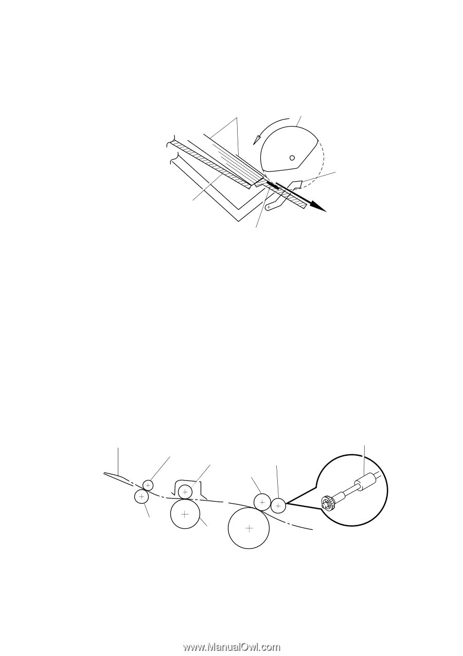
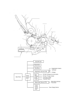
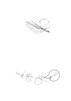
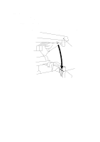
2.2 Paper Transfer 2.2.1 Paper Supply The pick-up roller picks up one sheet of paper from the paper tray at every one rotation and feeds it to the paper feed roller one by one. Papers Pick-up roller Registration sensor lever Hopper plate Separation pad Fig. 2.27 The paper is gripped between the pick-up roller and the separation pad and separated into individual sheets. The pick-up roller is directly connected to the sector gear, whose rotation is forcibly stopped by the gear stopper; when the pick-up solenoid is activated, the clutch mechanism is engaged by the solenoid ON/OFF and the sector gear is driven; when it has completed one full turn its rotation is stopped again by the gear stopper. The paper drawn out by the pick-up roller presses against the top of form sensor lever and the paper top position/absence of paper is detected by sensing the motion of the lever. 2.2.2 Paper Registration When paper picked up from the multi-purpose paper tray (MPT) presses against the top of form sensor actuator, the registration sensor lever is caused to turn, and the photo sensor detects this motion. With this signal from the sensor the paper feed roller is stopped of its rotation temporarily by the clutch. Then paper is fed to the nip point between the paper feed roller and the pinch roller in the multi purpose paper tray, and the skew of the paper is corrected by the bump of the leading edge of paper against the nip point. When the paper feed roller starts to rotated again by the motion of clutch, paper, leading edge of which has been aligned, is fed by the paper feed roller and is transported to the transfer roller. Paper Pinch roller Transfer roller Paper feed gear Idle gear Paper feed roller Paper feed roller Drum Clutch mechanism (engaged/released by the solenoid assembly) Released when the solenoid is ON and engaged when the solenoid is OFF. Fig. 2.28 II-25
-
 1
1 -
2
-
3
-
4
-
5
-
6
-
7
-
8
-
9
-
10
-
11
-
12
-
13
-
14
-
15
-
16
-
17
-
18
-
19
-
20
-
21
-
22
-
23
-
24
-
25
-
26
-
27
-
28
-
29
-
30
-
31
-
32
-
33
-
34
-
35
-
36
-
 37
37 -
 38
38 -
 39
39 -
 40
40 -
 41
41 -
 42
42 -
 43
43 -
 44
44 -
 45
45 -
 46
46 -
 47
47 -
48
-
49
-
50
-
51
-
52
-
53
-
54
-
55
-
56
-
57
-
58
-
59
-
60
-
61
-
62
-
63
-
64
-
65
-
66
-
67
-
68
-
69
-
70
-
71
-
72
-
73
-
74
-
75
-
76
-
77
-
78
-
79
-
80
-
81
-
82
-
83
-
84
-
85
-
86
-
87
-
88
-
89
-
90
-
91
-
92
-
93
-
94
-
95
-
96
-
97
-
98
-
99
-
100
-
101
-
102
-
103
-
104
-
105
-
106
-
107
-
108
-
109
-
110
-
111
-
112
-
113
-
114
-
115
-
116
-
117
-
118
-
119
-
120
-
121
-
122
-
123
-
124
-
125
-
126
-
127
-
128
-
129
-
130
-
131
-
132
-
133
-
134
-
135
-
136
-
137
-
138
-
139
-
140
-
141
-
142
-
143
-
144
-
145
-
146
-
147
-
148
-
149
-
150
-
151
-
152
-
153
-
154
 |
 |