Brother International HL-720 Service Manual - Page 75
No paper supplied, Insufficient output from high-voltage power supply unit
 |
View all Brother International HL-720 manuals
Add to My Manuals
Save this manual to your list of manuals |
Page 75 highlights
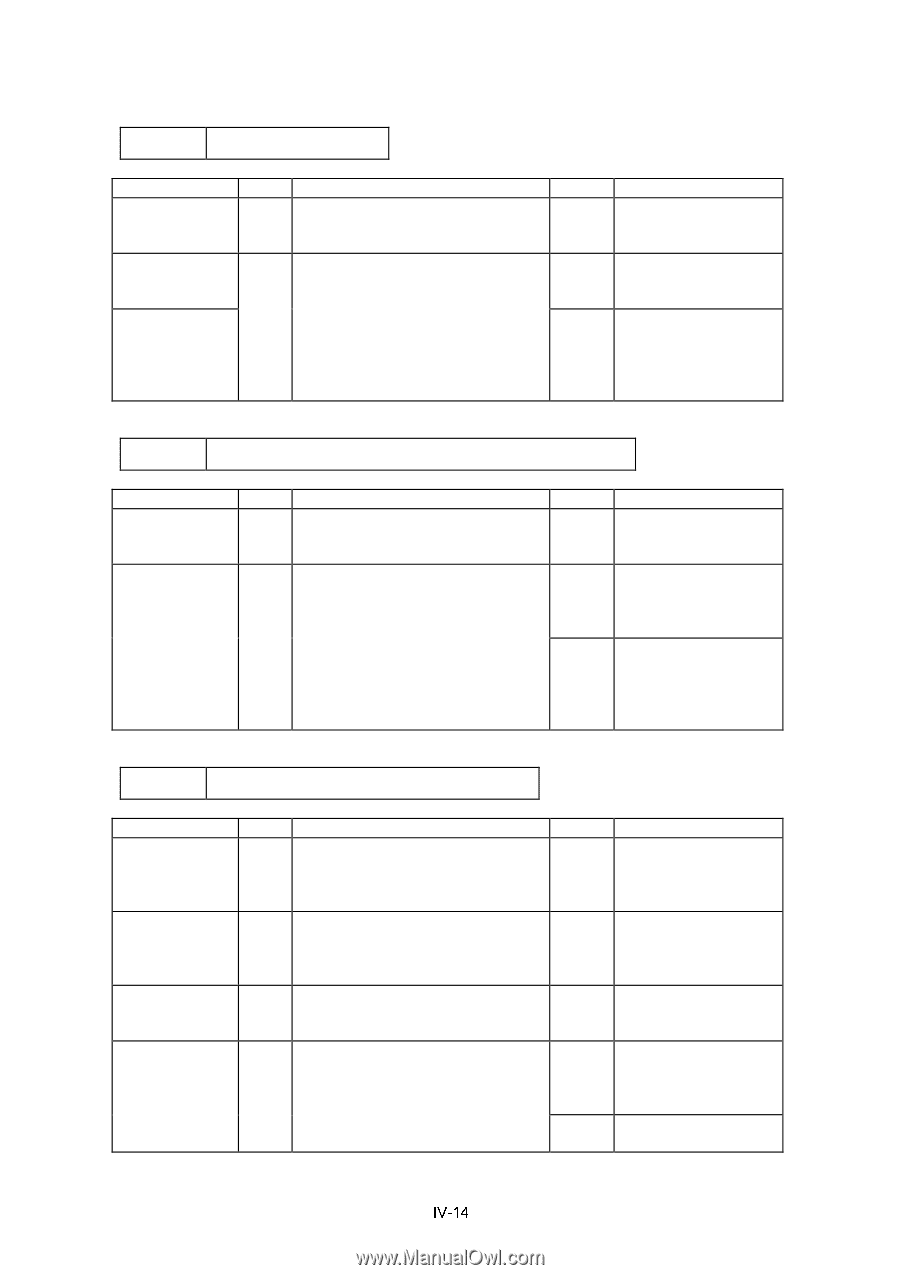
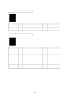
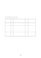
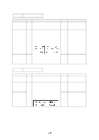
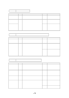
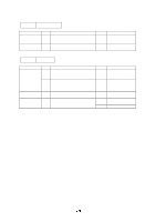
M-4 No paper supplied Possible cause Connection failure of connector Panel sensor circuit Paper pick-up clutch solenoid (SL501) Step Check 1 Is the contact of connector P6 on the panel sensor PCB good? 2 Set paper on the manual paper tray and press the test print button on the operation panel. Does the voltage between pins 1 (SOLENOID) and 2 (GND) of the P6 connector on the panel sensor PCB change from approx. 24 VDC to 0V within the specified time? Result Remedy No Reconnect the connector. No Replace the panel sensor PCB. Yes Replace the paper pick-up solenoid. M-5 Insufficient output from high-voltage power supply unit Possible cause High-voltage contact High-voltage power supply failure Step 1 2 Check Do any of the terminals on the highvoltage contacts have dirt or contact burns? Check the connection of the harness between the high-voltage power supply and the driver PCB is OK? Result Remedy Yes Clean the high-voltage contact. Yes Replace the highvoltage power supply PCB. No Reconnect the harness between the high-voltage power supply and the driver PCB. M-6 Fixing heater temperature not adjusted Possible cause Poor thermistor harness contact Blown thermal fuse Halogen heater lamp failure Thermistor failure Step 1 2 3 4 Check Are the connectors on the erase lamp PCB and the high-voltage power supply PCB secured correctly? Remove the fixing unit and measure the resistance between the input connectors. Is it open circuit? Remove the fixing unit and measure the resistance of the fixing unit lamp. Is it open circuit? Is the thermistor installed properly? Result Remedy No Connect the connectors securely. Yes Replace the fixing unit after unplugging the power cord from the power outlet. Yes Replace the halogen heater lamp. Yes Replace the fixing unit after unplugging the power cord from the power outlet. No Reinstall the halogen heater lamp.
-
 1
1 -
2
-
3
-
4
-
5
-
6
-
7
-
8
-
9
-
10
-
11
-
12
-
13
-
14
-
15
-
16
-
17
-
18
-
19
-
20
-
21
-
22
-
23
-
24
-
25
-
26
-
27
-
28
-
29
-
30
-
31
-
32
-
33
-
34
-
35
-
36
-
37
-
38
-
39
-
40
-
41
-
42
-
43
-
44
-
45
-
46
-
47
-
48
-
49
-
50
-
51
-
52
-
53
-
54
-
55
-
56
-
57
-
58
-
59
-
60
-
61
-
62
-
63
-
64
-
65
-
66
-
67
-
68
-
69
-
 70
70 -
 71
71 -
 72
72 -
 73
73 -
 74
74 -
 75
75 -
 76
76 -
 77
77 -
 78
78 -
 79
79 -
 80
80 -
81
-
82
-
83
-
84
-
85
-
86
-
87
-
88
-
89
-
90
-
91
-
92
-
93
-
94
-
95
-
96
-
97
-
98
-
99
-
100
-
101
-
102
-
103
-
104
-
105
-
106
-
107
-
108
-
109
-
110
-
111
-
112
-
113
-
114
-
115
-
116
-
117
-
118
-
119
-
120
-
121
-
122
-
123
-
124
-
125
-
126
-
127
-
128
-
129
-
130
-
131
-
132
-
133
-
134
-
135
-
136
-
137
-
138
-
139
-
140
-
141
-
142
-
143
-
144
-
145
-
146
-
147
-
148
-
149
-
150
-
151
-
152
-
153
-
154
 |
 |