Brother International HL-720 Service Manual - Page 40
Heater, Panel Sensor Circuit, Power Supply, Fig. 2.25
 |
View all Brother International HL-720 manuals
Add to My Manuals
Save this manual to your list of manuals |
Page 40 highlights
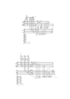
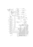
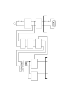
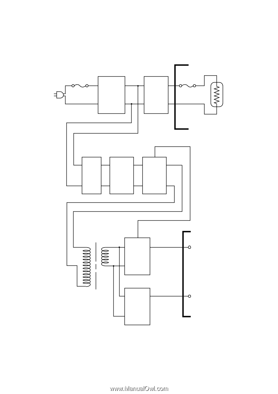
1.5 Power Supply The power supply uses the switching regulation system to generate the regulated DC power (+5V and +24V), which are converted from the AC line. (Heater) Fuse Lightning Surge Absorber Heater Circuit Thermal Fuse Lamp Feedback Line Filter Rectifier Oscillator 24V Regulation Circuit 5V Regulation Circuit Fig. 2.25 (Panel Sensor Circuit) 24V 5V II-23
-
 1
1 -
2
-
3
-
4
-
5
-
6
-
7
-
8
-
9
-
10
-
11
-
12
-
13
-
14
-
15
-
16
-
17
-
18
-
19
-
20
-
21
-
22
-
23
-
24
-
25
-
26
-
27
-
28
-
29
-
30
-
31
-
32
-
33
-
34
-
 35
35 -
 36
36 -
 37
37 -
 38
38 -
 39
39 -
 40
40 -
 41
41 -
 42
42 -
 43
43 -
 44
44 -
 45
45 -
46
-
47
-
48
-
49
-
50
-
51
-
52
-
53
-
54
-
55
-
56
-
57
-
58
-
59
-
60
-
61
-
62
-
63
-
64
-
65
-
66
-
67
-
68
-
69
-
70
-
71
-
72
-
73
-
74
-
75
-
76
-
77
-
78
-
79
-
80
-
81
-
82
-
83
-
84
-
85
-
86
-
87
-
88
-
89
-
90
-
91
-
92
-
93
-
94
-
95
-
96
-
97
-
98
-
99
-
100
-
101
-
102
-
103
-
104
-
105
-
106
-
107
-
108
-
109
-
110
-
111
-
112
-
113
-
114
-
115
-
116
-
117
-
118
-
119
-
120
-
121
-
122
-
123
-
124
-
125
-
126
-
127
-
128
-
129
-
130
-
131
-
132
-
133
-
134
-
135
-
136
-
137
-
138
-
139
-
140
-
141
-
142
-
143
-
144
-
145
-
146
-
147
-
148
-
149
-
150
-
151
-
152
-
153
-
154
 |
 |
II-23
1.5
Power Supply
The power supply uses the switching regulation system to generate the regulated DC
power (+5V and +24V), which are converted from the AC line.
Heater
Circuit
Thermal
Fuse
Lightning
Surge
Absorber
Feedback
Line
Filter
Fuse
Rectifier
Oscillator
24V
Regulation
Circuit
5V
Regulation
Circuit
24V
5V
Lamp
(Heater)
(Panel Sensor Circuit)
Fig. 2.25