Brother International HL-720 Service Manual - Page 125
Lift out the fan motor assy., Remove the four screws securing the drive unit.
 |
View all Brother International HL-720 manuals
Add to My Manuals
Save this manual to your list of manuals |
Page 125 highlights
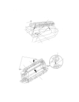
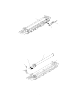
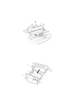
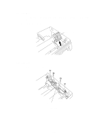
3.11 Fan Motor (1) Disconnect the connector from the high-voltage power supply PCB. ( It should have been disconnected already, see above) (2) Lift out the fan motor assy. Fan motor assy Fig. 3.12 3.12 Drive Unit (1) Remove the four screws securing the drive unit. Drive unit Fig. 3.13 III-10
-
 1
1 -
2
-
3
-
4
-
5
-
6
-
7
-
8
-
9
-
10
-
11
-
12
-
13
-
14
-
15
-
16
-
17
-
18
-
19
-
20
-
21
-
22
-
23
-
24
-
25
-
26
-
27
-
28
-
29
-
30
-
31
-
32
-
33
-
34
-
35
-
36
-
37
-
38
-
39
-
40
-
41
-
42
-
43
-
44
-
45
-
46
-
47
-
48
-
49
-
50
-
51
-
52
-
53
-
54
-
55
-
56
-
57
-
58
-
59
-
60
-
61
-
62
-
63
-
64
-
65
-
66
-
67
-
68
-
69
-
70
-
71
-
72
-
73
-
74
-
75
-
76
-
77
-
78
-
79
-
80
-
81
-
82
-
83
-
84
-
85
-
86
-
87
-
88
-
89
-
90
-
91
-
92
-
93
-
94
-
95
-
96
-
97
-
98
-
99
-
100
-
101
-
102
-
103
-
104
-
105
-
106
-
107
-
108
-
109
-
110
-
111
-
112
-
113
-
114
-
115
-
116
-
117
-
118
-
119
-
 120
120 -
 121
121 -
 122
122 -
 123
123 -
 124
124 -
 125
125 -
 126
126 -
 127
127 -
 128
128 -
 129
129 -
 130
130 -
131
-
132
-
133
-
134
-
135
-
136
-
137
-
138
-
139
-
140
-
141
-
142
-
143
-
144
-
145
-
146
-
147
-
148
-
149
-
150
-
151
-
152
-
153
-
154
 |
 |

III-10
3.11
Fan Motor
(1)
Disconnect the connector from the high-voltage power supply PCB. ( It should have
been disconnected already, see above)
(2)
Lift out the fan motor assy.
Fig. 3.12
3.12
Drive Unit
(1)
Remove the four screws securing the drive unit.
Fig. 3.13
Drive unit
Fan motor assy