Dell PowerVault 130T DLT Service Manual
Dell PowerVault 130T DLT Manual
 |
View all Dell PowerVault 130T DLT manuals
Add to My Manuals
Save this manual to your list of manuals |
Dell PowerVault 130T DLT manual content summary:
- Dell PowerVault 130T DLT | Service Manual - Page 1
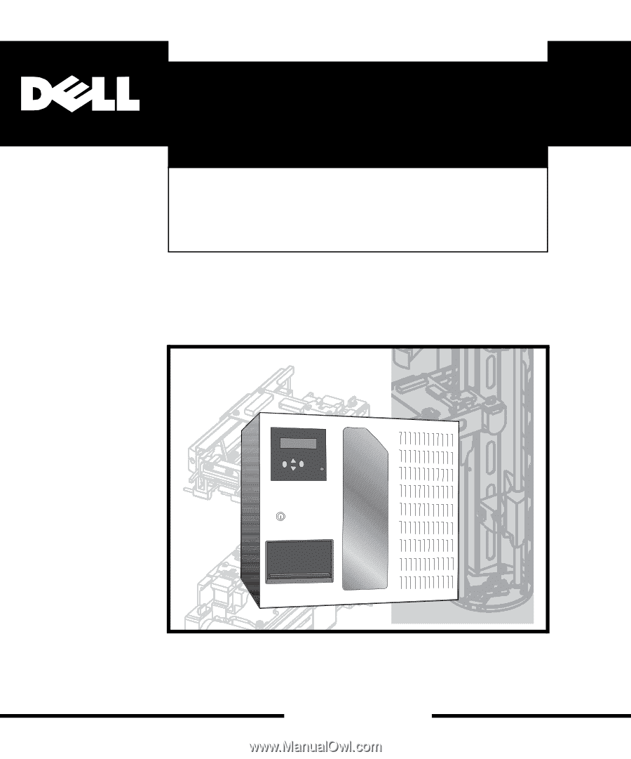
® Dell PowerVault® 130T Library SERVICE MANUAL www.dell.com - Dell PowerVault 130T DLT | Service Manual - Page 2
- Dell PowerVault 130T DLT | Service Manual - Page 3
® Dell PowerVault™ 130T Library SERVICE MANUAL www.dell.com - Dell PowerVault 130T DLT | Service Manual - Page 4
- Dell PowerVault 130T DLT | Service Manual - Page 5
PowerVault 130T Service Manual Contents Preface About This Manual Organization Alert Messages DLT Drives Chapter 2. TIPs, Diagnostics, and Procedures Trouble Isolation Procedures Examining FSCs Procedure TIP 0000: START TIP 1000: Power TIP 1010: Library Power Problems TIP 1020: Tape - Dell PowerVault 130T DLT | Service Manual - Page 6
PowerVault 130T Service Manual Loading Microcode Setting Tape Drive SCSI IDs Setting the Library SCSI ID Cleaning Tape Drives 2-10 2-12 2-13 2-14 Chapter 3. Removal and Replacement Preparation Powering On and Off the Library Removing the Front Door Required Tools Customer Replaceable - Dell PowerVault 130T DLT | Service Manual - Page 7
PowerVault 130T Service Manual Figures Figure 1-1. PowerVault 130T Library Figure 1-2. Front View of the PowerVault 130T Library Figure 1-3. Rear View of the PowerVault 130T Library Figure 1-4. PowerVault 130T Library Operator Panel Figure 1-5. PowerVault 130T Library Cell Locations Figure - Dell PowerVault 130T DLT | Service Manual - Page 8
PowerVault 130T Service Manual vi 4473D - Dell PowerVault 130T DLT | Service Manual - Page 9
PowerVault 130T Service Manual Preface About This Manual About This Manual This manual provides instructions for servicing the Dell PowerVault 130T Library. It is written for the technically trained personnel in charge of those operations. Organization This manual is organized as follows: - Dell PowerVault 130T DLT | Service Manual - Page 10
Publications PowerVault 130T Service Manual Related Publications Additional information is contained in the following publications: Publication Part Number PowerVault 130T Library User's Guide PowerVault 130T Quick Install Guide PowerVault 130T Product Information CD PowerVault 130T Safety - Dell PowerVault 130T DLT | Service Manual - Page 11
PowerVault 130T Service Manual Safety and ESD Safety The following pages cover three topics that are essential to all service activity: 1. Safety 2. Preventing electrostatic discharge (ESD) damage to equipment 3. Rack-mounted library safety and precautions Safety On-the-job safety is important; - Dell PowerVault 130T DLT | Service Manual - Page 12
Preventing Electrostatic Discharge Damage PowerVault 130T Service Manual Place your feet 31-46 centimeters (12-18 inches) apart and place one foot a little behind the other. Keep your back straight, because even light - Dell PowerVault 130T DLT | Service Manual - Page 13
PowerVault 130T Service Manual Preventing Electrostatic Discharge Damage Reinstall covers and close doors when equipment is not being serviced. If surface, such as a table or the floor next to the equipment to be serviced. 2. Attach one end of the ground cord to the work surface using the snap - Dell PowerVault 130T DLT | Service Manual - Page 14
Library Safety and Precautions PowerVault 130T Service Manual 4. Properly store the work surface and other Field Service Grounding Kit items. Rack-Mounted Library Safety and Precautions WARNING: The PowerVault 130T Library, with four tape positioning, supporting, and fastening the library in the - Dell PowerVault 130T DLT | Service Manual - Page 15
PowerVault 130T Service Manual Chapter 1. General Information Components The PowerVault 130T Library is a self-contained, rack-mountable, fully automated cartridge system that uses Digital Linear Tape (DLT) drives for data storage and retrieval. An automated cartridge system is a removable-medium, - Dell PowerVault 130T DLT | Service Manual - Page 16
Component Locations PowerVault 130T Service Manual Component Locations Following are descriptions of the major library components and their locations. Figure 1-2. Front View of the PowerVault 130T Library The locations below are described as you face the front of the library: Operator Panel - Dell PowerVault 130T DLT | Service Manual - Page 17
PowerVault 130T Service Manual Component Locations Figure 1-3. Rear View of the PowerVault 130T Library The locations below are described as you face the rear of the library: Hinged Access Door The hinged access door is between the electronics module and the drive slots. Drive and CYC card - Dell PowerVault 130T DLT | Service Manual - Page 18
Component Locations PowerVault 130T Service Manual Robot The robot is the mechanical assembly that moves cartridge tapes from storage cells to tape drives for data processing. It has the following components: Z column and motor Theta assembly and motor Hand/camera assembly For control and - Dell PowerVault 130T DLT | Service Manual - Page 19
PowerVault 130T Service Manual Component Locations The following functions are performed at the operator panel: Displaying library and tape drive status Configuring the library and tape drives Running diagnostic tests Displaying error information Message Lines Message Cap Locked Not Installed - Dell PowerVault 130T DLT | Service Manual - Page 20
Component Locations PowerVault 130T Service Manual In the figure, the number in library whenever it is required. Figure 1-5. PowerVault 130T Library Cell Locations Software The PowerVault 130T Library requires host-level software and device-level microcode to function. Numerous software solutions - Dell PowerVault 130T DLT | Service Manual - Page 21
PowerVault 130T Service Manual Component Locations Data archive Hierarchical storage management (HSM) Media management Disaster recovery The type of host-software solution chosen can optimize the performance of small to medium-sized networks, support multiple platforms, improve availability and - Dell PowerVault 130T DLT | Service Manual - Page 22
Component Locations PowerVault 130T Service Manual Table 1-1. DLT4000/DLT7000 Comparison Parameter DLT4000 Linear Search Speed 150 in./sec Average Rewind Time 70 sec Maximum Rewind Time 140 sec DLT7000 175 in./sec 60 sec 120 sec 1-8 4473D - Dell PowerVault 130T DLT | Service Manual - Page 23
routines, and other important procedures to help you service the PowerVault 130T Library. Trouble Isolation Procedures Most faults detected in the library result in a fault symptom code (FSC), four hexadecimal digits that identify an error. If you have a problem and know the FSC, you can replace the - Dell PowerVault 130T DLT | Service Manual - Page 24
Trouble Isolation Procedures PowerVault 130T Service Manual Sometimes a fault may exist without any indication of an FSC, such as A power problem A display problem An interface problem An intermittent or performance problem The following TIPs are guidelines to help diagnose and fix these problems - Dell PowerVault 130T DLT | Service Manual - Page 25
PowerVault 130T Service Manual TIP 0000: START TIP 0000: START The Start TIP is the beginning point for all of the following PowerVault 130T Library TIPs. Whenever a problem occurs and no FSC is displayed, begin the trouble isolation process here to help isolate and fix the problem. Problem A - Dell PowerVault 130T DLT | Service Manual - Page 26
TIP 1000: Power PowerVault 130T Service Manual TIP 1000: Power TIP 1000 is the starting point for power problems in the PowerVault 130T Library. Symptom Explanation Power problems are detected in some part of the library. Conditions That Could Cause This Problem Faulty switches, cables, or - Dell PowerVault 130T DLT | Service Manual - Page 27
PowerVault 130T Service Manual TIP 1010: Library Power Problems TIP 1010: Library Power Problems Use this TIP to troubleshoot and repair power problems with the library. Symptom Explanation The library does not power on. Conditions That Could Cause This Problem Electronics module is faulty. - Dell PowerVault 130T DLT | Service Manual - Page 28
TIP 1020: Tape Drive PowerVault 130T Service Manual TIP 1020: Tape Drive Use this TIP to troubleshoot and repair power problems with the tape drive. Symptom Explanation A tape drive does not power on. Conditions That Could Cause This Problem Faulty cable connection exists between the electronics - Dell PowerVault 130T DLT | Service Manual - Page 29
PowerVault 130T Service Manual TIP 2000: Operator Panel TIP 2000: Operator Panel Use this TIP to troubleshoot and repair problems with the operator panel. Symptom Explanation No display on the operator panel. Conditions That Could Cause This Problem . 4. Are the library fans turning? Yes: - Dell PowerVault 130T DLT | Service Manual - Page 30
: SCSI Interface PowerVault 130T Service Manual TIP 3000: SCSI Interface Use this TIP to troubleshoot and repair problems with the SCSI interface. Symptom Explanation The operating system does not recognize the library or the tape drives. Conditions That Could Cause This Problem SCSI cables may - Dell PowerVault 130T DLT | Service Manual - Page 31
PowerVault 130T Service Manual Library Diagnostics Library Diagnostics The following diagnostic routines are available from the "Library Diags" menu: Get-Put Loop Robot removes diagnostic tape from the CAP, moves, returns tape to the CAP. Mount Diagnostic Robot mounts diagnostic tape to a - Dell PowerVault 130T DLT | Service Manual - Page 32
Important Procedures PowerVault 130T Service Manual Important Procedures This section includes the following procedures that may sometimes be required: Loading Microde Setting tape drive SCSI IDs (from the operator panel) Setting the library SCSI ID (from the operator panel) Cleaning tape drives - Dell PowerVault 130T DLT | Service Manual - Page 33
PowerVault 130T Service Manual Important Procedures WARNING: Do not power down or reset the library while in the writing mode. 6. When the library Operator Panel displays Write OK..., push the Reset button on the operator panel. 7. The library will reboot and the operator panel will display - Dell PowerVault 130T DLT | Service Manual - Page 34
Important Procedures PowerVault 130T Service Manual 13. When the library Operator Panel Write OK..., push the Reset button on the operator panel. 14. The firmware update is complete. 15. The new Boot code and Functional Code will be displayed during the first 5 seconds of the library boot - Dell PowerVault 130T DLT | Service Manual - Page 35
PowerVault 130T Service Manual Important Procedures As an additional option under "Set Drive SCSI ID" you can set tape drives to be "On Bus" (the same SCSI bus as the library) or "Off Bus" (a different SCSI bus). The illustration below is an example of setting a drive off-bus. SCSI channel 1 (item - Dell PowerVault 130T DLT | Service Manual - Page 36
PowerVault 130T Service Manual Cleaning Tape Drives If a drive needs cleaning, a "Clean Me" message appears on the display for that drive. Follow this procedure to clean the drive. (When Auto Clean is enabled, the library automatically performs this operation. See the PowerVault 130T User's Guide - Dell PowerVault 130T DLT | Service Manual - Page 37
PowerVault 130T Service Manual Chapter 3. Removal and Replacement Preparation This chapter describes how to remove and replace the field replaceable units (FRUs) and customer replaceable units (CRUs) in the PowerVault 130T Library tests again to make sure the problem has been fixed. CAUTION: Review - Dell PowerVault 130T DLT | Service Manual - Page 38
Off the Library Powering On and Off the Library PowerVault 130T Service Manual Figure 3-1. Powering On and Off the Library To power-on the library: 1. Connect top right corner of the electronics module at the rear of the library. 2. Disconnect the power cable from the rear of the electronics module - Dell PowerVault 130T DLT | Service Manual - Page 39
PowerVault 130T Service Manual Removing the Front Door Removing the Front Door You will need to open the library front door to service the robotics and the arrays. The tape drives and the electronics module are serviced from the rear of the library. Figure 3-2. Removing the Library Front Door To - Dell PowerVault 130T DLT | Service Manual - Page 40
Required Tools PowerVault 130T Service Manual Required Tools The following tools are required for some all precautions and instructions. Table 3-1. CRU Locations and Functions Units Locations Functions Page #s DLT drive tray Left rear of the assembly library Holds tape drive and its - Dell PowerVault 130T DLT | Service Manual - Page 41
PowerVault 130T Service Manual Field Replaceable Units Table 3-2. Units Theta motor Z motor FRU Locations and Functions Locations Functions Inside the library, in the lower right corner. Provides power for theta movement of the robot. Inside the front of the library, at the top of the Z - Dell PowerVault 130T DLT | Service Manual - Page 42
CYC Card PowerVault 130T Service Manual CYC Card The CYC card FRU is mounted within the electronics module. The electronics module is inside the library and is accessed from the right rear side. You must remove the electronics module to service the CYC card. Tools required: ESD grounding kit Torx - Dell PowerVault 130T DLT | Service Manual - Page 43
card using the information you obtained from the View Configuration menu in step 1 of the removal procedure above. NOTE: Refer to Chapter 2 for instructions about setting library and tape drive SCSI IDs. A detailed configuration procedure is available in the PowerVault 130T User's Guide. 4473D 3-7 - Dell PowerVault 130T DLT | Service Manual - Page 44
CYO Card PowerVault 130T Service Manual CYO Card The CYO card FRU is behind the operator panel. The operator panel is on front of the library, to the left of the window and above the cartridge access port. You must remove the operator panel to access the CYO card and the - Dell PowerVault 130T DLT | Service Manual - Page 45
PowerVault 130T Service Manual Removal 1. Review the information under "Preparation" at the beginning of this chapter before starting this procedure. 2. Power off the library. Refer to "Powering On and Off the Library" on page 3-2. 3. Unlock and open the library front door. Refer to "Opening/Closing - Dell PowerVault 130T DLT | Service Manual - Page 46
Removal 12. Disconnect the magnetic sensor connector. 13. Squeeze the ears on the magnetic sensor switch and push it through the switch cutout as shown. PowerVault 130T Service Manual 3-10 4473D - Dell PowerVault 130T DLT | Service Manual - Page 47
PowerVault 130T Service Manual Replacement Magnetic Sensor Replacement 1. Push the magnetic sensor switch through the cutout as shown. 2. Connect the magnetic sensor connector. CYO Card Replacement 3. Align the four - Dell PowerVault 130T DLT | Service Manual - Page 48
9. Tighten the top two Keps nuts. 10. Install the two bottom Keps nuts. 11. Carefully close the library door to check for alignment. NOTE: Adjust the four mounting Keps nuts as necessary for alignment. 12. Proceed to the checkout procedures on page 3-43. PowerVault 130T Service Manual 3-12 4473D - Dell PowerVault 130T DLT | Service Manual - Page 49
PowerVault 130T Service Manual DLT Drive Tray Assembly DLT Drive Tray Assembly The DLT drive tray assembly FRUs are located in the tape drive slots at the left rear of the library. This assembly is also a CRU. Tools required: ESD wrist strap Flat blade screw driver Figure 3-5. DLT Drive Tray - Dell PowerVault 130T DLT | Service Manual - Page 50
DLT Drive Tray Assembly PowerVault 130T Service Manual Removal CAUTION: If the drives are daisy chained cable from the tape drive. CAUTION: Disconnect the tape drive interface cable, as described in the next step, before removing the tape drive. Make sure the cable is out of the tape drive bay by - Dell PowerVault 130T DLT | Service Manual - Page 51
PowerVault 130T Service Manual DLT Drive Tray Assembly 3. Disconnect the tape drive interface cable from the tape drive. NOTE: The tape drive interface cable (P980-P983) markings face the rear of the tape the two thumbscrews at the rear of the tape drive assembly. 6. Using both hands, remove the - Dell PowerVault 130T DLT | Service Manual - Page 52
DLT Drive Tray Assembly Replacement 1. Unpack the assembly and inspect it for damage such as bent, broken, or loose parts. 2. Verify that the tape drive tray assembly when it is not installed in the library. 5. To check terminator power (TERMPWR), remove the two PowerVault 130T Service Manual 4473D - Dell PowerVault 130T DLT | Service Manual - Page 53
PowerVault 130T Service Manual CAUTION: When sliding the drive into its bay, make sure the tape drive interface cable (with connectors P980-P983) is out of the way. Do not force the tape of the tape drive. CAUTION: The tape drive interface cable (P980-P983) marking faces the rear of the tape drive. - Dell PowerVault 130T DLT | Service Manual - Page 54
to the tape drive. 13. Close the hinged door at the rear of the library. 14. Tighten the two thumbscrews holding the hinged door closed. 15. Make sure all cables are installed and connectors are tight. 16. Proceed to the checkout procedures on page 3-43. PowerVault 130T Service Manual 3-18 4473D - Dell PowerVault 130T DLT | Service Manual - Page 55
PowerVault 130T Service Manual Electronics Module Electronics Module The electronics module FRU is inside the library on the right rear side as you face the rear of the library. The electronics module is also a CRU. Tools required: ESD grounding kit Torx driver and T-15 bit Flashlight Note paper - Dell PowerVault 130T DLT | Service Manual - Page 56
bottom of the electronics module using a Torx driver with a T-15 bit. 8. Loosen the three thumbscrews on the hinged access door at the rear of the library. 9. Open the door. PowerVault 130T Service Manual 3-20 4473D - Dell PowerVault 130T DLT | Service Manual - Page 57
PowerVault 130T Service Manual Disconnect the tape drive power cables library, verifying that all cables are disconnected. 13. Place the damaged electronics module on a flat, stable surface. WARNING: Do not apply power to the electronics module assembly when it is not installed in the PowerVault 130T - Dell PowerVault 130T DLT | Service Manual - Page 58
Electronics Module PowerVault 130T Service Manual Figure 3-8. Electronics Module Shown Removed from Library 3-22 4473D - Dell PowerVault 130T DLT | Service Manual - Page 59
PowerVault 130T Service Manual Electronics Module Replacement WARNING: Do not apply power to the electronics module assembly when it is not installed in the PowerVault 130T words appearing normally. 4. Slide the electronics module into the library. Use care not to snag loose cables. 5. Connect the - Dell PowerVault 130T DLT | Service Manual - Page 60
Electronics Module PowerVault 130T Service Manual 12. Power on the library. 13. Observe the front panel to ensure that power comes on to the library and tape drives. NOTE: The library must now be reconfigured. 14. Reconfigure the new CYC card using the information you obtained from the View - Dell PowerVault 130T DLT | Service Manual - Page 61
PowerVault 130T Service Manual Hand/Camera Assembly Hand/Camera Assembly The hand/camera assembly FRU mounts to the bearing block on the Z column. The hand/camera assembly is also a CRU. Removing and replacing the hand/camera assembly requires access through the library front door. The tools - Dell PowerVault 130T DLT | Service Manual - Page 62
ceiling of the library using a Torx driver with a T-15 bit. 7. Rotate the robot counterclockwise so that the hand extends beyond the front opening of the library. This allows more convenient access to the cable connectors on the CYH card (on the hand). PowerVault 130T Service Manual 3-26 4473D - Dell PowerVault 130T DLT | Service Manual - Page 63
PowerVault 130T Service Manual 8. Remove the screw holding the CYH card cover using a Torx driver. J20, and J18 connectors on the CYH card. 13. Rotate the robot clockwise so the hand is inside the library. 14. Carefully raise the hand to the top of the Z column assembly. 15. Remove the two screws - Dell PowerVault 130T DLT | Service Manual - Page 64
the base of the robot. (Optional but easier.) 21. Supporting the hand assembly with your left hand, remove the two library, making sure the hand motor clears the Z column and the Z belt. 23. Pull the hand/camera assembly out through the front opening of the library. PowerVault 130T Service Manual - Dell PowerVault 130T DLT | Service Manual - Page 65
PowerVault 130T Service Manual Replacement 1. Holding the assembly with your left hand, rotate it so the card side (top) faces the front of the library, making sure the hand motor clears the Z column and the Z belt. 2. Rotate the assembly until it clears the Z column and the Z belt and align it - Dell PowerVault 130T DLT | Service Manual - Page 66
. Secure the J20 connector under the cable clamp by flipping the clamp over the cable. 12. Rotate the robot so the hand is inside the library. 13. Carefully raise the hand to the top of the Z column assembly. PowerVault 130T Service Manual 3-30 4473D - Dell PowerVault 130T DLT | Service Manual - Page 67
PowerVault 130T Service Manual 14. Replace the CYH card cover over the CYH card, being careful to place the various cables under the card. 15. Replace the screw holding the CYH card cover using a Torx driver. 16. Install the two upper theta stops to the ceiling of the library using a Torx driver - Dell PowerVault 130T DLT | Service Manual - Page 68
Theta Motor PowerVault 130T Service Manual Theta Motor The theta motor FRU is at the bottom right corner of the library, inside the front door. The theta motor cables, but not the mounting bracket, are part of the FRU. Tools required: ESD grounding kit Torx driver - Dell PowerVault 130T DLT | Service Manual - Page 69
PowerVault 130T Service Manual Removal 1. Review the information under "Preparation" at the beginning of this chapter before starting this procedure. 2. Power off the library. Refer to "Powering On and Off the Library" on page 3-2. 3. Unlock, open, and remove the library front door. Refer to " - Dell PowerVault 130T DLT | Service Manual - Page 70
the library using a Torx driver with a T-15 bit. 9. Carefully move the hand to the top of the Z column. 10. Rotate the robot so that the hand extends beyond the front opening of the library. This allows access to the screw at the right rear of the theta motor mount. PowerVault 130T Service Manual - Dell PowerVault 130T DLT | Service Manual - Page 71
PowerVault 130T Service Manual 11. Remove the two screws from the theta motor mounting bracket (on the floor of the library) using a Torx driver with a T-15 bit, being careful not to damage orientation of the bracket (slotted alignment hole goes towards back of library). Theta Motor 4473D 3-35 - Dell PowerVault 130T DLT | Service Manual - Page 72
and mounting hole relative to the cable outlet on the motor. 3. Place the motor into the library so the theta belt loops around the motor pulley, and match the alignment slot and mounting hole by pressing on the belt retention flange on the tensioner. PowerVault 130T Service Manual 3-36 4473D - Dell PowerVault 130T DLT | Service Manual - Page 73
PowerVault 130T Service Manual 8. Install both theta stops to the ceiling of the library using a Torx driver with a T-15 bit. 9. Install the lower theta stop to the floor of the library using a Torx driver with a T-15 bit. 10. Connect the theta motor power cable connector. 11. Proceed to the - Dell PowerVault 130T DLT | Service Manual - Page 74
Z Motor PowerVault 130T Service Manual Z Motor The Z motor FRU is located at the top of the Z column and is attached by four screws to the Z kit Torx driver and T-15 bit Torque screwdriver capable of applying 10 in-lb. with a T-15 bit Key to the library front door Figure 3-11. Z Motor 3-38 4473D - Dell PowerVault 130T DLT | Service Manual - Page 75
PowerVault 130T Service Manual Removal 1. Review the information under "Preparation" at the beginning of this chapter before starting this procedure. 2. Power off the library. Refer to "Powering On and Off the Library" on page 3-2. 3. Unlock, open, and remove the library front door. Refer to Opening - Dell PowerVault 130T DLT | Service Manual - Page 76
from the motor shaft while holding the Z motor from behind. 10. Remove the motor by pushing the shaft through the cutout in the Z motor bracket. PowerVault 130T Service Manual 3-40 4473D - Dell PowerVault 130T DLT | Service Manual - Page 77
PowerVault 130T Service Manual Replacement 1. Insert the Z motor pulley through the cutout in the Z motor bracket so that the end of the pulley faces the front of the library. 2. Rest the pulley on the bottom of the cutout. The Z motor cable connector hangs toward the floor of the library. 3. Place - Dell PowerVault 130T DLT | Service Manual - Page 78
two tensioner adjustment screws, so you can replace the tensioner with the same belt tension as before. 8. Proceed to the checkout procedures on page 3-43. PowerVault 130T Service Manual 3-42 4473D - Dell PowerVault 130T DLT | Service Manual - Page 79
PowerVault 130T Service Manual Check-Out Procedures Check-Out Procedures To make sure that it is safe to resume library operation: 1. Make sure that all cards are installed and properly seated. 2. Make sure that all cables are installed and connectors are tight. 3. Visually check the library for - Dell PowerVault 130T DLT | Service Manual - Page 80
Check-Out Procedures PowerVault 130T Service Manual 3-44 4473D - Dell PowerVault 130T DLT | Service Manual - Page 81
PowerVault 130T Service Manual Appendix A. Supporting Information Specifications This appendix lists the specifications for the PowerVault 130T Library. Specifications Table A-1 through Table A-6 list the specifications of the PowerVault 130T Library. Table A-1. Functional Data Item - Dell PowerVault 130T DLT | Service Manual - Page 82
Specifications PowerVault 130T Service Manual Table A-2. Reliability Item Mean exchanges between failures (MEBF) Mean time to repair (MTTR) Measurement 1,000,000 less than 30 minutes Table A-3. Physical Specifications Item Width Height Depth Rear clearance, library to any wall or other cabinet - Dell PowerVault 130T DLT | Service Manual - Page 83
PowerVault 130T Service Manual Specifications Table A-6. Agency Certifications Category Certification CSA standard CAN/CSA-C22.2 no. 950-M93 Safety UL standard 1950, Third Edition EN60950 FCC #47, Part 15, - Dell PowerVault 130T DLT | Service Manual - Page 84
Specifications PowerVault 130T Service Manual A-4 4473D - Dell PowerVault 130T DLT | Service Manual - Page 85
PowerVault 130T Service Manual Glossary Glossary This glossary defines new or special terms. run offline tests within the library. differential A SCSI bus alternative with a maximum cable length or 25 meters (82 feet). disabled (1) Inactive. (2) Off. DLT Digital linear tape. E enabled (1) Active. - Dell PowerVault 130T DLT | Service Manual - Page 86
Glossary PowerVault 130T Service Manual fault symptom code Four-digit hexadecimal code generated in response to a subsystem error. FCC Federal Communications Commission. FRU Field replaceable unit. FSC See fault symptom code. L library An automated device for storing cartridge tapes. M m Meter. mm - Dell PowerVault 130T DLT | Service Manual - Page 87
PowerVault 130T Service Manual Index Index X-1 - Dell PowerVault 130T DLT | Service Manual - Page 88
Index PowerVault 130T Service Manual X-2 - Dell PowerVault 130T DLT | Service Manual - Page 89
PowerVault 130T Service Manual Index X-3 - Dell PowerVault 130T DLT | Service Manual - Page 90
Index PowerVault 130T Service Manual X-4 - Dell PowerVault 130T DLT | Service Manual - Page 91
PowerVault 130T Service Manual Index X-5 - Dell PowerVault 130T DLT | Service Manual - Page 92
Index PowerVault 130T Service Manual X-6 - Dell PowerVault 130T DLT | Service Manual - Page 93
PowerVault 130T Service Manual Index X-7 - Dell PowerVault 130T DLT | Service Manual - Page 94
Index PowerVault 130T Service Manual X-8 - Dell PowerVault 130T DLT | Service Manual - Page 95
- Dell PowerVault 130T DLT | Service Manual - Page 96
Printed in the U.S.A. ® 4473D
-
 1
1 -
 2
2 -
 3
3 -
 4
4 -
 5
5 -
 6
6 -
 7
7 -
8
-
9
-
10
-
11
-
12
-
13
-
14
-
15
-
16
-
17
-
18
-
19
-
20
-
21
-
22
-
23
-
24
-
25
-
26
-
27
-
28
-
29
-
30
-
31
-
32
-
33
-
34
-
35
-
36
-
37
-
38
-
39
-
40
-
41
-
42
-
43
-
44
-
45
-
46
-
47
-
48
-
49
-
50
-
51
-
52
-
53
-
54
-
55
-
56
-
57
-
58
-
59
-
60
-
61
-
62
-
63
-
64
-
65
-
66
-
67
-
68
-
69
-
70
-
71
-
72
-
73
-
74
-
75
-
76
-
77
-
78
-
79
-
80
-
81
-
82
-
83
-
84
-
85
-
86
-
87
-
88
-
89
-
90
-
91
-
92
-
93
-
94
-
95
-
96
 |
 |
www.dell.com
®
Dell PowerVault
®
130T Library
SERVICE MANUAL