Dell PowerVault 130T DLT Service Manual - Page 45
Removal, Refer to Opening/Closing/Removing
 |
View all Dell PowerVault 130T DLT manuals
Add to My Manuals
Save this manual to your list of manuals |
Page 45 highlights
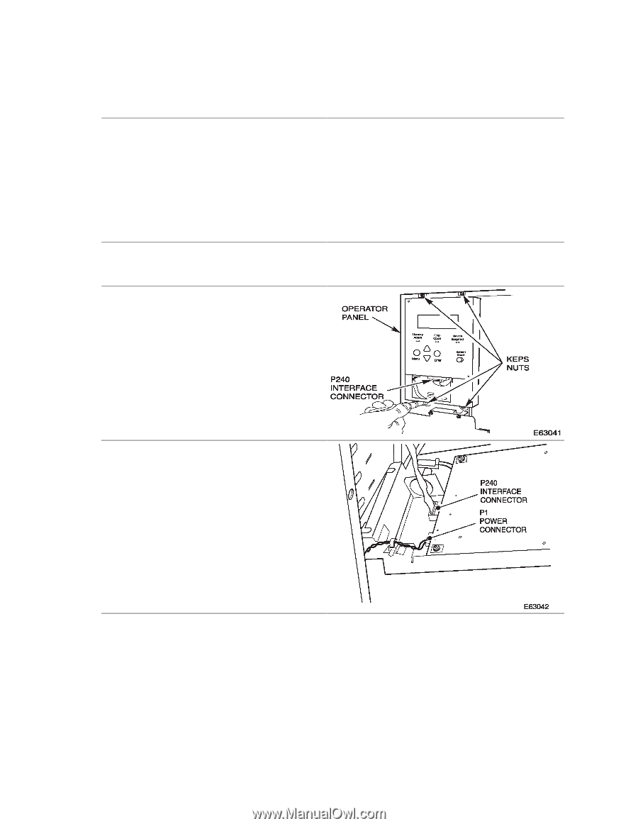
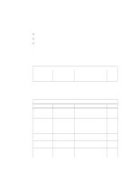
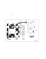
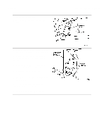
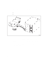
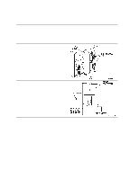
PowerVault 130T Service Manual Removal 1. Review the information under "Preparation" at the beginning of this chapter before starting this procedure. 2. Power off the library. Refer to "Powering On and Off the Library" on page 3-2. 3. Unlock and open the library front door. Refer to "Opening/Closing/Removing the Library Front Door" on page 3-3. CAUTION: Do not drop the Keps nuts into the library. 4. Remove the two bottom Keps nuts on the op panel. 5. Loosen, but do not remove the two top nuts. 6. Pull the bottom of the op panel forward to disengage the top two flanges. 7. Allow the op panel cover to tilt forward to provide access to the rear of the op panel. 8. Disconnect P240 connector on the ribbon cable. 9. Disconnect P1 power cable. CYO Card 4473D 3-9
-
 1
1 -
2
-
3
-
4
-
5
-
6
-
7
-
8
-
9
-
10
-
11
-
12
-
13
-
14
-
15
-
16
-
17
-
18
-
19
-
20
-
21
-
22
-
23
-
24
-
25
-
26
-
27
-
28
-
29
-
30
-
31
-
32
-
33
-
34
-
35
-
36
-
37
-
38
-
39
-
 40
40 -
 41
41 -
 42
42 -
 43
43 -
 44
44 -
 45
45 -
 46
46 -
 47
47 -
 48
48 -
 49
49 -
 50
50 -
51
-
52
-
53
-
54
-
55
-
56
-
57
-
58
-
59
-
60
-
61
-
62
-
63
-
64
-
65
-
66
-
67
-
68
-
69
-
70
-
71
-
72
-
73
-
74
-
75
-
76
-
77
-
78
-
79
-
80
-
81
-
82
-
83
-
84
-
85
-
86
-
87
-
88
-
89
-
90
-
91
-
92
-
93
-
94
-
95
-
96
 |
 |