Epson PowerLite Pro Z8150NL User Manual - Page 17
Wireless LAN unit, Monitor Out port
 |
View all Epson PowerLite Pro Z8150NL manuals
Add to My Manuals
Save this manual to your list of manuals |
Page 17 highlights
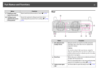
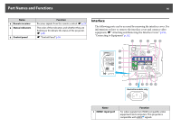
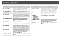
Part Names and Functions 17 Name Function 2 BNC input port For analog RGB signals from a computer and component video signals from other video sources. 3 Video input port For composite video signals from video sources. 4 S-Video input port For S-Video signals from video sources. 5 Cable holder When a thick heavy HDMI cable is connected to the HDMI input port, run a commercially available cable tie through this holder to prevent the cable from disconnecting. 6 Computer input port For analog RGB signals from a computer and component video signals from other video sources. 7 Power inlet Connects to the power cable. The shape may differ depending on your projector model. 8 Remote port Connects the optional remote control cable set and inputs signals from the remote control. When the remote control cable is plugged into this port, the remote receiver on the projector is disabled. 9 RS-232C port When controlling the projector from a computer or controller, connect it with an RS-232C cable. This port is for control use and should not normally be used. s p.133 10 Wireless LAN unit port Connects to the optional wireless LAN unit. s p.190 Name 11 Monitor Out port 12 SDI port (PowerLite Pro Z8450WUNL/ Z8455WUNL only) 13 HDMI2 input port 14 LAN port Function Outputs to an external monitor the analog signal from the computer connected to the Computer input port or the BNC input port. This is not available for component video signals or other signals being input to any port other than the Computer input port or the BNC input port. s p.185 For SDI signals from a video equipment. For video signals from HDMI compatible video equipment and computers. This projector is compatible with HDCPg signals. Connects a LAN cable to connect to a network. s p.185
-
 1
1 -
2
-
3
-
4
-
5
-
6
-
7
-
8
-
9
-
10
-
11
-
 12
12 -
 13
13 -
 14
14 -
 15
15 -
 16
16 -
 17
17 -
 18
18 -
 19
19 -
 20
20 -
 21
21 -
 22
22 -
23
-
24
-
25
-
26
-
27
-
28
-
29
-
30
-
31
-
32
-
33
-
34
-
35
-
36
-
37
-
38
-
39
-
40
-
41
-
42
-
43
-
44
-
45
-
46
-
47
-
48
-
49
-
50
-
51
-
52
-
53
-
54
-
55
-
56
-
57
-
58
-
59
-
60
-
61
-
62
-
63
-
64
-
65
-
66
-
67
-
68
-
69
-
70
-
71
-
72
-
73
-
74
-
75
-
76
-
77
-
78
-
79
-
80
-
81
-
82
-
83
-
84
-
85
-
86
-
87
-
88
-
89
-
90
-
91
-
92
-
93
-
94
-
95
-
96
-
97
-
98
-
99
-
100
-
101
-
102
-
103
-
104
-
105
-
106
-
107
-
108
-
109
-
110
-
111
-
112
-
113
-
114
-
115
-
116
-
117
-
118
-
119
-
120
-
121
-
122
-
123
-
124
-
125
-
126
-
127
-
128
-
129
-
130
-
131
-
132
-
133
-
134
-
135
-
136
-
137
-
138
-
139
-
140
-
141
-
142
-
143
-
144
-
145
-
146
-
147
-
148
-
149
-
150
-
151
-
152
-
153
-
154
-
155
-
156
-
157
-
158
-
159
-
160
-
161
-
162
-
163
-
164
-
165
-
166
-
167
-
168
-
169
-
170
-
171
-
172
-
173
-
174
-
175
-
176
-
177
-
178
-
179
-
180
-
181
-
182
-
183
-
184
-
185
-
186
-
187
-
188
-
189
-
190
-
191
-
192
-
193
-
194
-
195
-
196
-
197
-
198
-
199
-
200
-
201
-
202
-
203
-
204
-
205
-
206
-
207
-
208
-
209
-
210
-
211
-
212
-
213
-
214
-
215
-
216
-
217
-
218
-
219
-
220
-
221
-
222
-
223
-
224
-
225
-
226
-
227
-
228
-
229
-
230
-
231
-
232
-
233
-
234
-
235
-
236
-
237
-
238
-
239
-
240
-
241
-
242
-
243
-
244
-
245
-
246
-
247
-
248
-
249
-
250
-
251
-
252
-
253
-
254
 |
 |
