HP BL25/35/45p HP ProLiant Network Adapter Software and Configuration Guide - Page 50
Displaying Diagnostic Log, Network Test
 |
View all HP BL25/35/45p manuals
Add to My Manuals
Save this manual to your list of manuals |
Page 50 highlights
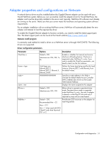
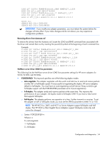
• Number of test passes-This option determines how many times a test runs. While the test is running, the information on the screen is continuously updated. When you press the Esc key, the test is cancelled and control is returned to the Test Adapter menu. • Diagnostic Log-This test is disabled by default. If enabled, the program will ask for a directory for the log file. The file it places here is named DIAGS.LOG. • Device Registers-Test patterns are written, read, and verified through the adapter's device registers to check proper functionality. • FIFO-This option writes test bit patterns to the adapter's FIFO buffers to check the FIFOs proper functionality. • EEPROM-This option tests both the readability of the EEPROM as well as the integrity of the data stored in the EEPROM. It reads EEPROM and calculates the checksum. This checksum is then compared to the checksum stored in the EEPROM. If the values are not identical, the test reports failure. • Interrupt-This option tests the adapter's ability to generate an interrupt and have it propagated through the system to the Programmable Interrupt Controller (PIC). The test triggers an interrupt by setting the interrupt cause register and then verifies that an interrupt has been triggered. On EFI, interrupts are not supported, Therefore, this test sets the interrupt cause register and reads the interrupt set register, which verifies the card internally registered an interrupt. • Loopback Tests-These options are internal loopback tests. These tests set the adapter in the appropriate loopback mode and send packets back through the adapter's receive circuitry and logic. • Link-This option checks to see whether or not the adapter has link. • Network Test-This option tests network communication. It looks for a responder and then sends packets. If no responder is found, then the test reports failure. If packets are received back from the responder, the test reports success. Displaying Diagnostic Log The Display Diagnostic Log option allows you to view a detailed report of the tests you just ran. When Diagnostic Log is enabled, test results are recorded in a log file named DIAGS.LOG. If it does not already exist, the test utility creates it. If it already exists, new data is appended to it. The DISPLAY DIAGNOSTIC LOG command displays the contents of the log file for your convenience. Each entry in the log file is time stamped. The test run banner identifies the tested adapter according to its bus slot address. Accessing the networking submenu The networking submenu allows you to setup the adapter as a responder and to detect a spanning tree on the network. • Setting up as a responder-This allows the user to set up the adapter as a responder so another system can perform the continuous network test. Selecting this option displays the transmit/receive screen. This test will fail if the adapter does not have link. Although you can use a variety of adapters as responders, and either connect directly (with a crossover cable) or through a switch, ideal results are obtained with a same-type adapter. When you press the Esc key, the responder operation is cancelled and control is immediately returned to the Test Adapter menu. • Detecting spanning tree-This allows the user to detect if a spanning tree is used on the network. Configuration and diagnostics 50
-
 1
1 -
2
-
3
-
4
-
5
-
6
-
7
-
8
-
9
-
10
-
11
-
12
-
13
-
14
-
15
-
16
-
17
-
18
-
19
-
20
-
21
-
22
-
23
-
24
-
25
-
26
-
27
-
28
-
29
-
30
-
31
-
32
-
33
-
34
-
35
-
36
-
37
-
38
-
39
-
40
-
41
-
42
-
43
-
44
-
 45
45 -
 46
46 -
 47
47 -
 48
48 -
 49
49 -
 50
50 -
 51
51 -
 52
52 -
 53
53 -
 54
54 -
 55
55 -
56
-
57
-
58
-
59
-
60
-
61
-
62
-
63
-
64
-
65
-
66
-
67
-
68
-
69
-
70
-
71
-
72
-
73
-
74
-
75
-
76
-
77
-
78
-
79
-
80
-
81
-
82
 |
 |