HP C7769B Service Manual
HP C7769B Manual
 |
View all HP C7769B manuals
Add to My Manuals
Save this manual to your list of manuals |
HP C7769B manual content summary:
- HP C7769B | Service Manual - Page 1
HP DesignJets 500 and 800 Series Large-Format Printers Service Manual - HP C7769B | Service Manual - Page 2
particular purpose. Hewlett-Packard shall not be liable for errors contained herein or for incidental or consequential damages in connection with the furnishing, performance, or use of this material. The procedures described in this manual are to be performed by HP-qualified service personnel only - HP C7769B | Service Manual - Page 3
1 HP DesignJets 500 and 800 Series Large-Format Printers Service Manual - HP C7769B | Service Manual - Page 4
Using this Manual Purpose This Service Manual contains information necessary to test, calibrate and service: n HP DesignJet 500 Printer - 24" Model (P/N C7769B) n HP DesignJet 500 Printer - 42" Model (P/N C7770B) n HP DesignJet 500PS Printer - 24" Model (P/N C7769C) n HP DesignJet 500PS Printer - 42 - HP C7769B | Service Manual - Page 5
Cover Sensors are not Working 1-3 The Line Sensor has Problems Detecting Media 1-3 Troubleshooting Paper-Axis Shutdowns 1-4 Problems with the Vacuum Fan 1-5 Vacuum suction much lower at high altitudes 1-5 HP-GL/2 color differences in different HP DesignJet Printers 1-6 Banding at variable extreme - HP C7769B | Service Manual - Page 6
Printer Causing Repetitive Printhead Problems? 3-16 Is the User Replacing the Printheads too Early? 3-18 Troubleshooting Repetitive Ink Cartridge Messages 3-20 Troubleshooting Repetitive Printhead Error Messages 3-21 Printhead Error Codes 3-22 Summary of Solving Ink Supplies Problems 3-23 Service - HP C7769B | Service Manual - Page 7
24 Pinch-Wheel Assemblies 7-26 Scan-Axis Motor 7-28 Drive Roller Encoder Sensor 7-30 Print Platen Assembly 7-32 Carriage Assembly 7-34 Vacuum Fan 7-36 Interconnect Cable 7-38 Paper-Axis Motor 7-40 Drive Roller 7-42 Miscellaneous Items 7-44 HP DesignJets 500 and 800 Series Printers Service Manual 5 - HP C7769B | Service Manual - Page 8
PCA 8-50 Service Station and Aerosol Fan 8-52 Cutter Guide 8-55 Print Platen 8-56 Service Station Holder 8-57 Interconnect Cable 8-59 Ink Supply Tubes 8-60 Vacuum Fan 8-64 Pinch-Arm 8-66 Pinch-Arm Mechanism 8-67 Pinch-Arm Lever 8-69 6 HP DesignJets 500 and 800 Series Printers Service Manual - HP C7769B | Service Manual - Page 9
System 10-3 Introduction 10-3 Hardware Description 10-3 Power Supply Unit (PSU) 10-5 Front Panel 10-6 Ink Delivery System (IDS) 10-7 Ink Supply Station (ISS) 10-7 Tubes Assembly 10-9 Service Station 10-10 Glossary Index Table of Contents HP DesignJets 500 and 800 Series Printers Service Manual 7 - HP C7769B | Service Manual - Page 10
Table of Contents 8 HP DesignJets 500 and 800 Series Printers Service Manual - HP C7769B | Service Manual - Page 11
differences in different HP DesignJet Printers 1-6 Banding at variable extreme environmental conditions 1-6 The Priming Procedure Fails 1-7 Using the Power Switch LED to Troubleshoot 1-10 Using the Boot-Up Sequence to Troubleshoot 1-12 HP DesignJets 500 and 800 Series Printers Service Manual 1-1 - HP C7769B | Service Manual - Page 12
that certain Calibrations are required even if an Assembly has been disassembled to gain access to another Assembly or Component. For information on the Service Calibrations and how to use them see Chapter 5 - Service Calibrations. 1-2 HP DesignJets 500 and 800 Series Printers Service Manual - HP C7769B | Service Manual - Page 13
if the Line Sensor detects it. 2 Excessive ink deposits on the Print Platen surface can fool the sensor by reflecting the light. Clean the Print Platen. 3 The Line Sensor is damaged or faulty. Replace the Carriage Assembly ⇒ Page 8-78. HP DesignJets 500 and 800 Series Printers Service Manual 1-3 - HP C7769B | Service Manual - Page 14
, the sheet will be loaded correctly, and the Printer will detect that media has been loaded (using the Media Sensor). Therefore the problem must be the Encoder Sensor and the solution would be to replace the Encoder Sensor ⇒ Page 8-38. 1-4 HP DesignJets 500 and 800 Series Printers Service Manual - HP C7769B | Service Manual - Page 15
loading problems (high probability). n Roll Media loading problems (low probability). The solution to this would be to change the Vacuum force by changing the Altitude setting. This can be done via the front panel ⇒ Set-up Menu / Altitude. HP DesignJets 500 and 800 Series Printers Service Manual - HP C7769B | Service Manual - Page 16
of the Drive Roller does not correspond to the same conditions that the calibration was done in. To solve the problem, try the following: n Perform the Accuracy Calibration in the new environmental conditions (Refer to the User's Guide). 1-6 HP DesignJets 500 and 800 Series Printers Service Manual - HP C7769B | Service Manual - Page 17
this problem is Ink Cartridges with a faulty valve. Even if the priming process fails, the Printer will try to verify whether the priming process has been completed by moving the Carriage to the access position and you will see the following HP DesignJets 500 and 800 Series Printers Service Manual - HP C7769B | Service Manual - Page 18
Printer considers that the priming procedure has been completed successfully and will proceed to the Printhead replacement process. If you select NOT all with ink the Printer will react differently depending on the source of the problem: 1-8 HP DesignJets 500 and 800 Series Printers Service Manual - HP C7769B | Service Manual - Page 19
Printer (around 20 cc of ink). Remove the Ink Cartridges and release the Tubes Bracket from the Ink Supply Station and check if there is ink in this area. For more information on this problem, refer to System Error 93:10 on Page 2-19. HP DesignJets 500 and 800 Series Printers Service Manual 1-9 - HP C7769B | Service Manual - Page 20
problems. You should only use the LED to troubleshoot when the Printer problem has been detected with the previous firmware upgrade. Try resending the firmware upgrade file. LED Flashes twice every few seconds - The Printer cannot detect 1-10 HP DesignJets 500 and 800 Series Printers Service Manual - HP C7769B | Service Manual - Page 21
the Electronics Module ⇒ Page 8-24. LED Flashes 5 times every few seconds - This indicates that the Main PCA has failed. Replace the Electronics Module ⇒ Page 8-24. HP DesignJets 500 and 800 Series Printers Service Manual 1-11 - HP C7769B | Service Manual - Page 22
to Troubleshoot When you Power On the Printer, the Printer performs the Boot-Up sequence which initializes the major components of the Printer. If Initializing a portion of the Firmware. Initializing various components of the Main PCA. 1-12 HP DesignJets 500 and 800 Series Printers Service Manual - HP C7769B | Service Manual - Page 23
the Printer ON. This will give you access to some of the Service Tests and Utilities without having to complete the System Initialization (if you perform some of the tests, they will need to initialize the relevant part of the System). HP DesignJets 500 and 800 Series Printers Service Manual 1-13 - HP C7769B | Service Manual - Page 24
flashing) indicates that the Formatter/ Accessory Card is alive. If it stops flashing, it means that the Formatter/Accessory Card has failed and should be replaced. n The green LED indicates that there is power being supplied to the 1-14 HP DesignJets 500 and 800 Series Printers Service Manual - HP C7769B | Service Manual - Page 25
Power Supply Unit. n The red LED will flash a few times when the Printer is started up but if it stays lit (all the time) or flashes continuously, then this indicates that the Formatter/Accessory Card is faulty and should be replaced. HP DesignJets 500 and 800 Series Printers Service Manual 1-15 - HP C7769B | Service Manual - Page 26
Troubleshooting 1-16 HP DesignJets 500 and 800 Series Printers Service Manual - HP C7769B | Service Manual - Page 27
64:04 2-14 71:04 2-15 71:06 2-15 72:04 2-16 73:04 2-16 79:04 2-17 81:01 2-17 81:11 2-17 85:10 2-18 86:01 2-18 86:11 2-18 86:13 2-19 87:13 2-19 93:10 2-19 HP DesignJets 500 and 800 Series Printers Service Manual 2-1 - HP C7769B | Service Manual - Page 28
2 digits of the System Error Code: Code 01 02 03 04 05 06 07 08 11 Component/System Main PCA/Electronics Module Carriage/Carriage PCA Power Supply Unit Network Card Formatter Hard Disk Drive Interconnect PCA Front Panel Trailing Cable 2-2 HP DesignJets 500 and 800 Series Printers Service Manual - HP C7769B | Service Manual - Page 29
Roller Encoder Sensor Ink Leak Detector Color Sensor Media Type Sensor Language Interpreting Input/Output through Parallel Port Input/Output through Network Card Input/Output through USB Port Memory Management Generic Firmware Servo HP DesignJets 500 and 800 Series Printers Service Manual 2-3 - HP C7769B | Service Manual - Page 30
10 Replace 11 Reseat/Reconnect/Clean/Adjust (manually) 12 Calibrate/Adjust (using Automatic Process) On-Site 13 Power OFF visit 14 Upgrade System Firmware required 15 Upgrade Driver 16 Add Accessory 19 Wrong Part Installed 2-4 HP DesignJets 500 and 800 Series Printers Service Manual - HP C7769B | Service Manual - Page 31
for Set-up menu Menu Back Enter 2 Press the ↑ or ↓ key until the front panel highlights Log. Press the Enter key. Set-up menu Expansion cards I/O set-up front panel Altitude = 0-1000 m. Log Menu Back Enter HP DesignJets 500 and 800 Series Printers Service Manual 2-5 - HP C7769B | Service Manual - Page 32
5 The front panel displays information on the selected item. Error log Error code: 21:10 linefeed.c, 217 Date: 20-Sep-01 NOTE To view information on another Error Code, press BACK and the front panel will return to the previous screen 2-6 HP DesignJets 500 and 800 Series Printers Service Manual - HP C7769B | Service Manual - Page 33
Module are NOT bent. System Error: 01:12 Problem Description: The EEROM is not configured correctly (the product number may be missing). Corrective Action: Configure the EEROM correctly using the EEROM setup utility ⇒ Page 4-16. HP DesignJets 500 and 800 Series Printers Service Manual 2-7 - HP C7769B | Service Manual - Page 34
. Corrective Action: Try the following: n Switch the Printer Off and wait a few minutes. Switch the Printer On again and check if the Error Code has disappeared. n If the Error Code continues, replace the Carriage Assembly ⇒ Page 8-78. 2-8 HP DesignJets 500 and 800 Series Printers Service Manual - HP C7769B | Service Manual - Page 35
⇒ Page 8-20. System Error: 05:10 Error (Only applicable to HP DesignJet 500 Series) Problem Description: HP-GL/2 Accessory Card failure. Corrective Action: Power OFF the Printer and replace the HP-GL/2 Accessory Card ⇒ Page 8-20. HP DesignJets 500 and 800 Series Printers Service Manual 2-9 - HP C7769B | Service Manual - Page 36
Assembly. Corrective Action: Try the following: n Remove ALL the Printheads and clean the flex contacts on the Printheads and in the Carriage Assembly. n Replace ALL the Printheads. n Replace the Carriage Assembly ⇒ Page 8-78. 2-10 HP DesignJets 500 and 800 Series Printers Service Manual - HP C7769B | Service Manual - Page 37
process while depressurizing. Corrective Action: Replace the Ink Supply Station ⇒ Page 8-48. System Error: 41:10 Problem Description: Paper-Axis Motor failure. Corrective Action: Replace the Paper-Axis Motor ⇒ Page 8-84. HP DesignJets 500 and 800 Series Printers Service Manual 2-11 - HP C7769B | Service Manual - Page 38
: Vacuum Fan not detected. Corrective Action: Reconnect the Vacuum Fan. System Error: 56:10 Problem Description: Drive Roller Encoder Sensor error. Corrective Action: Replace the Drive Roller Encoder Sensor ⇒ Page 8-38. 2-12 HP DesignJets 500 and 800 Series Printers Service Manual - HP C7769B | Service Manual - Page 39
. - Firmware release of the Printer (use the Printer Information utility ⇒ Page 4-26). - The complete Error Code information, including the linefeed where the error occurred (use the Error Log utility to obtain this information ⇒ Page 2-5). HP DesignJets 500 and 800 Series Printers Service Manual - HP C7769B | Service Manual - Page 40
Firmware release of the Printer (use the Printer Information utility ⇒ Page 4-26). - The complete Error Code information, including the linefeed where the error occurred (use the Error Log utility to obtain this information ⇒ Page 2-5). 2-14 HP DesignJets 500 and 800 Series Printers Service Manual - HP C7769B | Service Manual - Page 41
Information utility ⇒ Page 4-26). If necessary, install more memory into the Formatter. n If the problem continues, try processing the file in the PC instead of the Printer (select Avoid out of memory in Advanced options in the Driver). HP DesignJets 500 and 800 Series Printers Service Manual 2-15 - HP C7769B | Service Manual - Page 42
Firmware release of the Printer (use the Printer Information utility ⇒ Page 4-26). - The complete Error Code information, including the linefeed where the error occurred (use the Error Log utility to obtain this information ⇒ Page 2-5). 2-16 HP DesignJets 500 and 800 Series Printers Service Manual - HP C7769B | Service Manual - Page 43
by a paper jam, then try the following: n Perform the Paper Advance Test ⇒ Page 4-10. System Error: 81:11 Problem Description: Paper-Axis shutdown (during the Paper Advance test). Corrective Action: Refer to Error Code 81:01. HP DesignJets 500 and 800 Series Printers Service Manual 2-17 - HP C7769B | Service Manual - Page 44
: 85:10 Problem Description: Paper-Axis Encoder Carriage Movement test ⇒ Page 4-8. System Error: 86:11 Problem Description: Carriage-Axis shutdown (during the Carriage Movement test). Corrective Action: Refer to Error Code 86:01. 2-18 HP DesignJets 500 and 800 Series Printers Service Manual - HP C7769B | Service Manual - Page 45
the procedure. If it takes too long to complete the procedure and there is no leak in the Printer, then replace the Ink Cartridges. If it takes a short time to complete the procedure, then replace the Ink Supply Tubes ⇒ Page 8-60. HP DesignJets 500 and 800 Series Printers Service Manual 2-19 - HP C7769B | Service Manual - Page 46
System Error Codes 2-20 HP DesignJets 500 and 800 Series Printers Service Manual - HP C7769B | Service Manual - Page 47
Is the User Replacing the Printheads too Early? 3-18 Troubleshooting Repetitive Ink Cartridge Messages 3-20 Troubleshooting Repetitive Printhead Error Messages 3-21 Printhead Error Codes 3-22 Summary of Solving Ink Supplies Problems 3-23 HP DesignJets 500 and 800 Series Printers Service Manual 3-1 - HP C7769B | Service Manual - Page 48
The Ink Cartridges for the HP DesignJet 500 and 800 Series Printers require no maintenance or cleaning. As long as each Ink Cartridge is inserted correctly into its slot, the ink will flow to the Printheads. The Ink Cartridges are number coded as follows: n HP No.10 for the Black Ink Cartridge. n HP - HP C7769B | Service Manual - Page 49
quality such as lines or dots missing from text / graphics, go to page Page 6-4, Performing the Troubleshooting Procedure. Identifying the Components The following illustration will help you identify the components of the ink supplies. HP DesignJets 500 and 800 Series Printers Service Manual 3-3 - HP C7769B | Service Manual - Page 50
is printing. They should only be removed when the Printer is ready for you to replace them. The front panel will guide you through the removal and installation procedure. See page Page 3-6, When Should You Replace the Ink Cartridges? 3-4 HP DesignJets 500 and 800 Series Printers Service Manual - HP C7769B | Service Manual - Page 51
throughout the Printhead life. n Do not touch the end of the Ink Cartridge which is inserted into the Printer as there may be a small amount of ink on the connection. n Avoid storing partially used Ink Cartridges on their ends. HP DesignJets 500 and 800 Series Printers Service Manual 3-5 - HP C7769B | Service Manual - Page 52
date has been reached, the Printer will stop working and you will need to install a new Ink Cartridge in order to proceed. If this message appears repetitively, refer to Page 320, Troubleshooting Repetitive Ink Cartridge Messages. 3-6 HP DesignJets 500 and 800 Series Printers Service Manual - HP C7769B | Service Manual - Page 53
a problem but the Printer does not know which one it is. In order to identify and replace the failing Printhead, try the following: 1 Select replace Printheads from the front panel. 2 Open the Carriage cover and remove ALL the Printheads. HP DesignJets 500 and 800 Series Printers Service Manual - HP C7769B | Service Manual - Page 54
the maximum recovery action. The user can continue using the Printer even with the Printhead Warning message but will not get the maximum Print Quality that the Printer is designed to provide, unless he replaces the worn out Printhead. 3-8 HP DesignJets 500 and 800 Series Printers Service Manual - HP C7769B | Service Manual - Page 55
Enter 5 The front panel displays information on the selected Ink Cartridge. Black cartridge info Model: HP Black No. 10 Status: inserted Expiration date: 15-Aug-2002 Serial number: 06-02-1232651 Ink level: 63cc (91%) Menu Back Enter HP DesignJets 500 and 800 Series Printers Service Manual 3-9 - HP C7769B | Service Manual - Page 56
Color calibration Troubleshooting Align printheads Replace printheads Menu Back Enter 3 Press the ↑ or ↓ key until the front panel highlights Printheads. Press the Enter key. Information Menu Ink cartridges Printheads Back Enter 3-10 HP DesignJets 500 and 800 Series Printers Service Manual - HP C7769B | Service Manual - Page 57
has been performed since the last Printhead replacement. n Whether Color Calibration has been performed since the last Printhead replacement. n Whether a Paper Jam was ever detected while this particular Printhead was installed. HP DesignJets 500 and 800 Series Printers Service Manual 3-11 - HP C7769B | Service Manual - Page 58
can be done; Flashing cross; the wrong Ink Cartridge is installed, and must be replaced before any further printing can be done. Sand Clock; the Ink Cartridge will expire in X amount of days. The X is displayed at the top of the screen. 3-12 HP DesignJets 500 and 800 Series Printers Service Manual - HP C7769B | Service Manual - Page 59
still decide if the Print Quality is good enough for them). ? Question Mark; one of the Printheads has experienced a problem but the Printer does not know which one it is. Refer to Page 3-7 to determine which Printhead has failed. HP DesignJets 500 and 800 Series Printers Service Manual 3-13 - HP C7769B | Service Manual - Page 60
ENTER for Set-up menu Back Enter 2 Press the ↑ or ↓ key until the front panel highlights Log. Press the Enter key. Set-up menu Expansion cards I/O set-up front panel Altitude = 0-1000 m. Log Menu Back Enter 3-14 HP DesignJets 500 and 800 Series Printers Service Manual - HP C7769B | Service Manual - Page 61
Printhead is unknown. n Removed - OK: The Printhead was replaced correctly after the minimum life expectancy of the Printhead was reached, without any error being reported. n Removed - too early: The Printhead was replaced before the HP DesignJets 500 and 800 Series Printers Service Manual - HP C7769B | Service Manual - Page 62
Printhead needs replacing or not after performing various levels of recovery actions. After performing a recovery action, the Printhead will be encoded with either 1, 2 or 3 (depending on the strength of the recovery action performed). 3-16 HP DesignJets 500 and 800 Series Printers Service Manual - HP C7769B | Service Manual - Page 63
PH Info - Black #4 Ink used: 127 cc (24%) Usage time: 65 days P/H cleaning: 3 Error code: Removal date: 24-Nov-00 As you can see in the above example, all the Printheads were removed before the minimum life expectancy was reached (Ink HP DesignJets 500 and 800 Series Printers Service Manual 3-17 - HP C7769B | Service Manual - Page 64
History Utility you can determine if the Customer is replacing the Printheads too early as follows: 1 Enter the Printhead History Utility and Select the color of the Printhead that is experiencing the replacement problem. In the 3-18 HP DesignJets 500 and 800 Series Printers Service Manual - HP C7769B | Service Manual - Page 65
Page 6-4) to determine if Printheads need replacing or not. Emphasize that performing the Troubleshooting procedure could recover the Printhead if it is printing badly, therefore the User wouldn't need to buy new Printheads frequently. HP DesignJets 500 and 800 Series Printers Service Manual 3-19 - HP C7769B | Service Manual - Page 66
Tubes could be broken in which case replace the Ink Supply Tubes ⇒ Page 8-60. 3 If the message still continues to appear, perform the Ink Supply Station test ⇒ Page 4-6. If the test fails, replace the Ink Supply Station ⇒ Page 8-48. 3-20 HP DesignJets 500 and 800 Series Printers Service Manual - HP C7769B | Service Manual - Page 67
based solutions only). 3 If the message continues to appear after cleaning the Carriage Assembly and the Printhead, replace the Printhead again. 4 If the message still continues to appear, replace the Carriage Assembly ⇒ Page 8-78. HP DesignJets 500 and 800 Series Printers Service Manual 3-21 - HP C7769B | Service Manual - Page 68
will die soon. Acumen Error - Replace faulty Printhead, check other Printheads or Cartridges (only if all Printheads fail with this Error Code). Try the above recommened actions one at a time and check if the problem disappears. 3-22 HP DesignJets 500 and 800 Series Printers Service Manual - HP C7769B | Service Manual - Page 69
and the Carriage Assembly using a damp cloth. n Replace the Printhead with a new one. You Cannot Insert the Ink Cartridge Into the Printer 1 Ensure that you have the correct HP Ink Cartridge that is suitable for the HP DesignJet 500/800 Series Printer. 2 Ensure that the Ink Cartridge is the - HP C7769B | Service Manual - Page 70
Ink Supplies Troubleshooting 3-24 HP DesignJets 500 and 800 Series Printers Service Manual - HP C7769B | Service Manual - Page 71
4-4 Ink Supply Station 4-6 Carriage Movement 4-8 Paper Advance Test 4-10 Service Utilities 4-13 Entering the Service Utilities Menu 4-14 EEROM Setup 4-16 Turn Drive Roller 4-21 Unlock Carriage 4-22 Prime Tubes 4-23 Change Cutter 4-24 Change Ink Tubes 4-25 Printer Information 4-26 HP DesignJets 500 - HP C7769B | Service Manual - Page 72
the Printer ON. This will give you access to some of the Service Tests and Utilities without having to complete the System Initialization (if you perform some of the tests, they will need to initialize the relevant part of the System). 4-2 HP DesignJets 500 and 800 Series Printers Service Manual - HP C7769B | Service Manual - Page 73
Quality is poor at anytime, the Troubleshooting procedure should be performed which will determine whether the Printhead needs replacing (by marking it with an exclamation mark) or not after performing various levels of recovery actions. HP DesignJets 500 and 800 Series Printers Service Manual 4-3 - HP C7769B | Service Manual - Page 74
list of Service Tests. 3 Once inside the Service Tools Menu, press the ↑ or ↓ key until the front panel displays Service Tests and then press Enter. Service tools Menu Service tests Service calibrations Service utilities Back Enter 4-4 HP DesignJets 500 and 800 Series Printers Service Manual - HP C7769B | Service Manual - Page 75
Service Tests and Utilities 4 Press the Enter key to begin a specific test when the required Service Test is highlighted. Service tests Troubleshooting Aerosol Fan test Ink Supply Station Paper advance test Carriage movement test Menu Back Enter HP DesignJets 500 and 800 Series Printers Service - HP C7769B | Service Manual - Page 76
Station Paper advance test Carriage movement test Menu Back Enter 2 Once the test starts, the following message will appear on the Front Panel. Open the Ink Cartridge door and remove ALL the Ink Cartridges: ISS Test Remove all the ink cartridges 4-6 HP DesignJets 500 and 800 Series Printers - HP C7769B | Service Manual - Page 77
message will appear on the Front Panel: ISS Test Test result 22:10 Faulty INK SUPPLY STATION Call HP representative In this case, to resolve the problem, try the following: 1 Replace the Ink Supply Station Assembly ⇒ Page 8-48. HP DesignJets 500 and 800 Series Printers Service Manual 4-7 - HP C7769B | Service Manual - Page 78
analyze the data received while performing the test. Once the data has been analyzed, the following message will appear on the Front Panel: Carriage movement Carriage movement test Ready to display results. Press ENTER Menu Back Enter 4-8 HP DesignJets 500 and 800 Series Printers Service Manual - HP C7769B | Service Manual - Page 79
Service Tests and Utilities 4 If you press Enter, the Front Panel will display a list of the different the Front Panel will display the results of the Stabilization distance: Stabilization distance results Stabilizat. dist. (mm): XX HP DesignJets 500 and 800 Series Printers Service Manual 4-9 - HP C7769B | Service Manual - Page 80
will be displayed (press Enter to continue to the next stage of the test): Paper Advance test Menu Paper-axis motor test passed. Press ENTER to continue Back Enter WARNING IF THIS TEST PASSES, DO NOT REPLACE THE PAPERAXIS MOTOR. 4-10 HP DesignJets 500 and 800 Series Printers Service Manual - HP C7769B | Service Manual - Page 81
Sensor, then the test has failed and the following message will be displayed: Paper Advance test System error 56:10 Roller encoder sensor failed In this case, to resolve the problem, replace the Drive Roller Encoder Sensor ⇒ Page 8-38. HP DesignJets 500 and 800 Series Printers Service Manual 4-11 - HP C7769B | Service Manual - Page 82
: Paper Advance test Moving Drive Roller. Please wait 6 Once the test is completed, the results will be displayed on the front panel: Test results Average PWM: XX Std dev PWM: X Average value of the PWM Standard deviation value of the PWM 4-12 HP DesignJets 500 and 800 Series Printers Service - HP C7769B | Service Manual - Page 83
a position where it makes the removal of the Ink Supply Tubes much easier. 7 Printer Information ⇒ Page 4-26 The purpose of this Utility is the following: n Report basic parameters for call qualification. n Identify potential problems. HP DesignJets 500 and 800 Series Printers Service Manual 4-13 - HP C7769B | Service Manual - Page 84
of Service Tests. 3 Once inside the Service Tools Menu, press the ↑ or ↓ key until the front panel displays Service Utilities and then press Enter. Service Menu Menu Service tests Service calibrations Service utilities Back Enter 4-14 HP DesignJets 500 and 800 Series Printers Service Manual - HP C7769B | Service Manual - Page 85
Service Tests and Utilities 4 Press the Enter key to begin a specific utility when the required Service Utility is highlighted. Service utilities Change ink tubes Unlock Carriage Turn Drive Roller Prime tubes EEROM Setup Menu Back Enter HP DesignJets 500 and 800 Series Printers Service Manual - HP C7769B | Service Manual - Page 86
model number. Use the arrow keys to scroll through the selections, and press Enter to make the selection. Once the selection is made the 4-16 HP DesignJets 500 and 800 Series Printers Service Manual - HP C7769B | Service Manual - Page 87
Service Tests and Utilities symbol √ will appear next to the selected model number. To return to the EEROM setup options menu, press Back. Select model number C7769B C7770B C7779B √ C7780B New: ESB75_ 5 6 7 Menu Back Enter HP DesignJets 500 and 800 Series Printers Service Manual 4-17 - HP C7769B | Service Manual - Page 88
not detect a formatter, the Printer will not allow you to enter this utility and will display the following message on the front panel. Font type setting is not available for this type of printer Press BACK or ENTER to return to menu 4-18 HP DesignJets 500 and 800 Series Printers Service Manual - HP C7769B | Service Manual - Page 89
Reset usage counter Scan axis usage: Paper axis usage: Serv. Station usage: Spittoon usage: Pinch-lift usage Cutter usage: Carriage usage: Ink usage: Menu Back Enter b Once been reset, enter the Printer Information utility ⇒ Page 4-26. HP DesignJets 500 and 800 Series Printers Service Manual 4-19 - HP C7769B | Service Manual - Page 90
Model Number and the Font Type (without re-entering this information, the Printer will NOT work). DO NOT SWITCH THE PRINTER OFF AND ON AGAIN BEFORE RE-ENTERING THESE VALUES. Also you will need to perform the Factory Advance Calibration. 4-20 HP DesignJets 500 and 800 Series Printers Service Manual - HP C7769B | Service Manual - Page 91
on the front panel. Press Enter if you want to return to the Service Utility menu or press Back if you want to continue turning the Drive Roller. Turning Drive Roller Turning Drive Roller stopped. Press ENTER to finish or BACK to resume HP DesignJets 500 and 800 Series Printers Service Manual 4-21 - HP C7769B | Service Manual - Page 92
The Carriage will remain uncapped until another action (e.g. loading paper or replacing Printheads) is selected which returns the Printer to normal operation. Make sure you leave the Carriage in a locked position once the repair is completed. 4-22 HP DesignJets 500 and 800 Series Printers Service - HP C7769B | Service Manual - Page 93
On the Printer, the Printer will initialize and then display the following message. You will need to remove the normal Printheads and replace them with Start-up Printheads. Open window and remove normal printheads to prepare ink system HP DesignJets 500 and 800 Series Printers Service Manual 4-23 - HP C7769B | Service Manual - Page 94
Change Cutter Change ink tubes Unlock Carriage Turn Drive Roller Prime tubes Menu Back Enter 2 The Carriage will move to the left hand side of the Printer, pick up the Cutter and move it to a position where the Cutter can be replaced. 4-24 HP DesignJets 500 and 800 Series Printers Service Manual - HP C7769B | Service Manual - Page 95
switch the Printer OFF before starting to change the Ink Supply Tubes. 1. Switch off the machine 2. Refer to the Service Manual to replace tubes The next time the Printer is switched ON, it will automatically start the Priming process. HP DesignJets 500 and 800 Series Printers Service Manual 4-25 - HP C7769B | Service Manual - Page 96
Ink used: Black 6 cc Cyan 4 cc Magenta 4 cc Yellow 3 cc Scan axis usage: 21% Paper axis usage: 23% Serv. Station usage: 19% Spittoon usage: 12% Pinch-Lift usage: 10% Cutter usage: 26% Carriage usage: 12% Ink usage: 2% Menu Back Enter 4-26 HP DesignJets 500 and 800 Series Printers Service Manual - HP C7769B | Service Manual - Page 97
). n Paper usage - The amount of media used by the Printer. n Ink usage - The amount of Ink used by the Printer. n Scan axis usage - Number of Scan-Axis cycles represented as a percentage over the maximum number of Scan-Axis cycles that the HP DesignJets 500 and 800 Series Printers Service Manual - HP C7769B | Service Manual - Page 98
over the maximum number of Printhead insertions that the Printer is designed to support. If the percentage is more than 100% and the Printer is experiencing problems then try the following: 1 Replace the Carriage Assembly ⇒ Page 8-78. 4-28 HP DesignJets 500 and 800 Series Printers Service Manual - HP C7769B | Service Manual - Page 99
Service Calibrations 5 Service Calibrations 5-2 Entering the Service Calibrations Menu 5-3 Printhead Alignment (includes PPS Calibration) 5-5 Color Calibration 5-7 Advance Calibration 5-9 Factory Advance Calibration 5-11 HP DesignJets 500 and 800 Series Printers Service Manual 5-1 - HP C7769B | Service Manual - Page 100
in order to avoid print quality problems like banding. The values from the Calibration will then be stored in the EEROM and the user can restore the Printer to these values by selecting "Restore factory" in the Advance Calibration menu. 5-2 HP DesignJets 500 and 800 Series Printers Service Manual - HP C7769B | Service Manual - Page 101
of Service Tests. 3 Once inside the Service Tools Menu, press the ↑ or ↓ key until the front panel displays Service calibrations and then press Enter. Service tools Menu Service tests Service calibrations Service utilities Back Enter HP DesignJets 500 and 800 Series Printers Service Manual - HP C7769B | Service Manual - Page 102
Calibrations 4 Press the Enter key to begin a specific calibration when the required Service Calibration is highlighted. Service calibrations Align printheads Color calibration Advance calibration Factory advance cal. Menu Back Enter 5-4 HP DesignJets 500 and 800 Series Printers Service Manual - HP C7769B | Service Manual - Page 103
Service calibrations Align printheads Color calibration Advance calibration Factory advance cal. Menu Back Enter 2 The following message will appear asking you if you want to perform the Standard alignment or the Special alignment. Select HP DesignJets 500 and 800 Series Printers Service Manual - HP C7769B | Service Manual - Page 104
to poor Print Quality it will try and recover the Printheads and retry the Printhead Alignment. If the Calibration continues to fail due to Printhead problems, the Printer will mark the failing Printheads (but they will still be usable). 5-6 HP DesignJets 500 and 800 Series Printers Service Manual - HP C7769B | Service Manual - Page 105
ink system for the specific media loaded into the Printer. The Printer stores the calibration data for each type of media that has been calibrated since the Printer was switched ON. If the Printer Press ENTER to continue Menu Back Enter HP DesignJets 500 and 800 Series Printers Service Manual 5-7 - HP C7769B | Service Manual - Page 106
that you DO NOT use transparent media when performing the Color Calibration. n Clean the Line Sensor and try the Calibration again. n Make sure that the Window is closed when you perform the Color Calibration. 5-8 HP DesignJets 500 and 800 Series Printers Service Manual - HP C7769B | Service Manual - Page 107
. Paper not present. Load paper to print calibration pattern Press ENTER to continue 4 The Printer will start to print the Accuracy Calibration Pattern and the following message will be displayed on the front panel: Job management menu Calibrating HP DesignJets 500 and 800 Series Printers Service - HP C7769B | Service Manual - Page 108
while the Printer measures the pattern: Job management menu Calibrating 9 Once the calibration is completed, the following message will be displayed: Calibration finished successfully. Press ENTER to continue Menu Back Enter 5-10 HP DesignJets 500 and 800 Series Printers Service Manual - HP C7769B | Service Manual - Page 109
Ink Supply Station are replaced. Perform the Factory Advance Calibration as follows: Make sure you load HP High Gloss Photo Paper or HP Bright White Inkjet Paper in to the Printer cal. Menu Create pattern Measure pattern Back Enter HP DesignJets 500 and 800 Series Printers Service Manual 5-11 - HP C7769B | Service Manual - Page 110
) Direction of paper when loading (measuring pattern) 6 In order to measure the pattern that has been printed, load the pattern into the Printer with the printed side up and with the dotted line at the top (that is, rotated 90º). 5-12 HP DesignJets 500 and 800 Series Printers Service Manual - HP C7769B | Service Manual - Page 111
while the Printer measures the pattern: Job management menu Calibrating 9 Once the calibration is completed, the following message will be displayed: Calibration finished successfully. Press ENTER to continue Menu Back Enter HP DesignJets 500 and 800 Series Printers Service Manual 5-13 - HP C7769B | Service Manual - Page 112
Service Calibrations 5-14 HP DesignJets 500 and 800 Series Printers Service Manual - HP C7769B | Service Manual - Page 113
Defects Found Using the Troubleshooting Procedure 6-8 Long Term Color Bleeding (Glossy Papers) 6-9 Solving Color Accuracy problems 6-9 Color Consistency problems 6-9 Media 6-10 There are Smears or Scratching on the Printed Media 6-10 HP DesignJets 500 and 800 Series Printers Service Manual 6-1 - HP C7769B | Service Manual - Page 114
of the problem is related with the print mode defined with the Non-HP Driver try the following: n Print the same sample using the Non-HP driver and their normal media. n Print one of the internal demos using HP Media and configuring 6-2 HP DesignJets 500 and 800 Series Printers Service Manual - HP C7769B | Service Manual - Page 115
. 7 Service Accuracy Calibration n Perform "Service Accuracy calibration" using HP High-Gloss Photo Paper. Do NOT use any other type of media apart from HP High Gloss Photo Paper or Bright White InkJet Paper when performing the Accuracy Calibration. HP DesignJets 500 and 800 Series Printers Service - HP C7769B | Service Manual - Page 116
driver for example. Performing the Troubleshooting Procedure 1 To perform the Troubleshooting procedure press the ↑ or ↓ key until the front panel displays the Ink Menu and then press Enter. Ink menu Ink cartridges Menu Back Enter 6-4 HP DesignJets 500 and 800 Series Printers Service Manual - HP C7769B | Service Manual - Page 117
is a problem with the dashed lines, you are prompted to perform the Advance Calibration procedure. 7 If you indicate that the broken lines in Diagnostic Print A are OK, then examine the blocks of color carefully and when prompted by HP DesignJets 500 and 800 Series Printers Service Manual 6-5 - HP C7769B | Service Manual - Page 118
2 Diagnostic Prints show any problems, it could be that the Print Quality problem is caused by a wrong setting in the software, or maybe the print job should have been printed with Print Quality set to Best instead of Normal or Draft. 6-6 HP DesignJets 500 and 800 Series Printers Service Manual - HP C7769B | Service Manual - Page 119
Are the colored patterns in Diagnostic Print B OK? Yes (all OK) No Yes No problems detected If possible, Printer tries to Clean Printheads If Printheads have been cleaned 3 times, the Printer recommends that you Replace Printheads HP DesignJets 500 and 800 Series Printers Service Manual 6-7 - HP C7769B | Service Manual - Page 120
correctly. What to Configure Printer Front-Panel Menu HP driver (Windows, AutoCAD or Mac) Non-HP drivers (Software RIPs) Configuration Setting printer default.) n Make sure that the media setting matches the media loaded in the printer. 6-8 HP DesignJets 500 and 800 Series Printers Service Manual - HP C7769B | Service Manual - Page 121
the lines fuzzy and bleary. This will be because of the humidity conditions that the printer is working under: n Ask the customer to change the paper that they are printing with. or n Remove the printer from the high humidity conditions. HP DesignJets 500 and 800 Series Printers Service Manual 6-9 - HP C7769B | Service Manual - Page 122
one or both of the options 'auto rotate' and 'inked area'. If the above fails to solve the problem of smears and scratching, change the media that the customer is using to a non-paper based media such as HP High Gloss Photo Paper. 6-10 HP DesignJets 500 and 800 Series Printers Service Manual - HP C7769B | Service Manual - Page 123
Pinch-Wheel Assemblies 7-26 Scan-Axis Motor 7-28 Drive Roller Encoder Sensor 7-30 Print Platen Assembly 7-32 Carriage Assembly 7-34 Vacuum Fan 7-36 Interconnect Cable 7-38 Paper-Axis Motor 7-40 Drive Roller 7-42 Miscellaneous Items 7-44 HP DesignJets 500 and 800 Series Printers Service Manual 7-1 - HP C7769B | Service Manual - Page 124
Parts and Diagrams Printer Support Reference on Drawing 1 2 3 4 - Printer Support HP Part Number Quantity Description/ Assembly 1 X-Brace Assembly (24" Model) 1 X-Brace Assembly (42" Model) 1 Hardware Kit (Includes Screw Drivers) 7-2 HP DesignJets 500 and 800 Series Printers Service Manual - HP C7769B | Service Manual - Page 125
Parts and Diagrams 4 3 3 1 2 Figure 1: Printer Support HP DesignJets 500 and 800 Series Printers Service Manual 2 7-3 - HP C7769B | Service Manual - Page 126
-60160 C7769-60161 1 Right Hand Cover - Grey (HP DesignJet 500 Series Only) 1 Right Hand Cover - Black (HP DesignJet 800 Series Only) 5 Screws 1 Trim Kit (Includes the front and back trims for the left and right sides) 1 Front Panel 7-4 HP DesignJets 500 and 800 Series Printers Service Manual - HP C7769B | Service Manual - Page 127
Parts and Diagrams 4 1 2 3 Figure 2: Right Hand Cover HP DesignJets 500 and 800 Series Printers Service Manual 7-5 - HP C7769B | Service Manual - Page 128
C7779-60158 0624-0771 C7769-60160 1 Left Hand Cover - Grey (HP DesignJet 500 Series Only) 1 Left Hand Cover - Black (HP DesignJet 800 Series Only) 5 Screws 1 Trim Kit (Includes the front and back trims for the left and right sides) 7-6 HP DesignJets 500 and 800 Series Printers Service Manual - HP C7769B | Service Manual - Page 129
Parts and Diagrams 1 3 2 2 3 Figure 3: Left Hand Cover HP DesignJets 500 and 800 Series Printers Service Manual 7-7 - HP C7769B | Service Manual - Page 130
500 Series Only) C7779-60154 1 Top Cover - Black (HP DesignJet 800 Series Only) C7780-60154 1 Top Cover - Black (HP DesignJet 800 Series Only) 2 0515-1743 2 3 Screws 3 C7769-60167 2 3 Media Deflectors (comes as a kit) 7-8 HP DesignJets 500 and 800 Series Printers Service Manual - HP C7769B | Service Manual - Page 131
Parts and Diagrams 1 2 Figure 4: Top Cover and Deflectors HP DesignJets 500 and 800 Series Printers Service Manual 3 7-9 - HP C7769B | Service Manual - Page 132
Reference on Drawing 1 2 3 Rollfeed Module HP Part Number Quantity Description/Comments C7769-60162 0624-0771 C7769-60184 C7770-60008 1 Rollfeed Module Kit 6 Screw Plas M4 1in 1 Spindle (24" Model Only) 1 Spindle (42" Model Only) 7-10 HP DesignJets 500 and 800 Series Printers Service Manual - HP C7769B | Service Manual - Page 133
Parts and Diagrams 3 2 1 1 2 Figure 5: Rollfeed Module HP DesignJets 500 and 800 Series Printers Service Manual 7-11 - HP C7769B | Service Manual - Page 134
Reference on Drawing 1 2 3 Back Platen Assembly HP Part Number Quantity Description/Comments C7769-60155 C7770-60155 0624-0769 C7769-60168 1 Back Platen (24" Model Only) 1 Back Platen (42" Model Only) 2 Screw 1 Media Sensor 7-12 HP DesignJets 500 and 800 Series Printers Service Manual - HP C7769B | Service Manual - Page 135
Parts and Diagrams 1 2 3 Figure 6: Back Platen Assembly HP DesignJets 500 and 800 Series Printers Service Manual 7-13 - HP C7769B | Service Manual - Page 136
Part Number Quantity Description/Comments C7779-60144 0515-2200 J3113A C7769-60143 C7772A 1 Electronics Module 3 Screw Tap M3 x 10 mm 1 EIO Card 1 Formatter (HP DesignJet 500PS, 800 and 800PS Only) 1 Formatter (HP DesignJet 500 Only) 7-14 HP DesignJets 500 and 800 Series Printers Service Manual - HP C7769B | Service Manual - Page 137
Parts and Diagrams 1 4 2 3 Figure 7: Electronics Module HP DesignJets 500 and 800 Series Printers Service Manual 7-15 - HP C7769B | Service Manual - Page 138
Parts and Diagrams Power Supply Reference on Drawing 1 2 Power Supply HP Part Number Quantity Description/Comments C7769-60145 0515-2200 1 Power Supply Unit 3 Screw Tap M3 x 10 mm 7-16 HP DesignJets 500 and 800 Series Printers Service Manual - HP C7769B | Service Manual - Page 139
Parts and Diagrams 2 1 Figure 8: Power Supply HP DesignJets 500 and 800 Series Printers Service Manual 7-17 - HP C7769B | Service Manual - Page 140
0515-2200 0515-1743 1 Cutter Assembly 1 Cutter Bushing 1 Cutter Guide (24" Model Only) 1 Cutter Guide (42" Model Only) 1 Cutter Guide Bracket and Left Encoder Holder Kit 1 Screw (Cutter Guide Bracket) 2 Screw (Left Encoder Holder) 7-18 HP DesignJets 500 and 800 Series Printers Service Manual - HP C7769B | Service Manual - Page 141
Parts and Diagrams 1 4 3 2 6 5 4 Figure 9: Cutter Assemblies HP DesignJets 500 and 800 Series Printers Service Manual 7-19 - HP C7769B | Service Manual - Page 142
HP Part Number Quantity Description/Comments C7769-60153 C7770-60153 C7769-60148 0624-0769 C7769-60164 1 Tubes Assembly (24" Model Only) 1 Tubes Assembly (42" Model Only) 1 Ink Supply Station 1 Screw Plas 6-19 0.5 in 1 Start-up Printheads 7-20 HP DesignJets 500 and 800 Series Printers Service - HP C7769B | Service Manual - Page 143
Parts and Diagrams 4 1 3 2 Figure 10: Ink Delivery System HP DesignJets 500 and 800 Series Printers Service Manual 7-21 - HP C7769B | Service Manual - Page 144
and Spittoon Reference on Drawing 1 2 3 Service Station and Spittoon HP Part Number Quantity Description/Comments C7769-60149 0624-0769 C7769-60165 1 Service Station/Aerosol Fan 2 Screw Plas 6-19 0.5 in 1 Left Spittoon Assembly 7-22 HP DesignJets 500 and 800 Series Printers Service Manual - HP C7769B | Service Manual - Page 145
Parts and Diagrams 2 1 3 Figure 11: Service Station and Spittoon HP DesignJets 500 and 800 Series Printers Service Manual 7-23 - HP C7769B | Service Manual - Page 146
Holder HP Part Number Quantity Description/Comments C7769-60156 0515-2282 0624-0769 C7769-60173 0624-0769 C7769-60176 1 Service Station Holder (Right Hand Bracket) 4 Screw 2 Screw 1 Interconnect PCA 1 Screw 1 Tensioner Assembly Kit 7-24 HP DesignJets 500 and 800 Series Printers Service Manual - HP C7769B | Service Manual - Page 147
Parts and Diagrams 5 4 1 6 2 3 Figure 12: Service Station Holder HP DesignJets 500 and 800 Series Printers Service Manual 7-25 - HP C7769B | Service Manual - Page 148
Assemblies Reference on Drawing 1 2 3 4 5 Pinch-Wheel Assemblies HP Part Number Quantity Description/Comments C7769-60181 C7770-60015 C7769-60175 0515-2521 -Arm Sensor 1 Screw * Pinch Arm Mechanism includes the Pinch Arm Lever. 7-26 HP DesignJets 500 and 800 Series Printers Service Manual - HP C7769B | Service Manual - Page 149
Parts and Diagrams 4 5 1 3 2 Figure 13: Pinch-Wheel Assemblies HP DesignJets 500 and 800 Series Printers Service Manual 7-27 - HP C7769B | Service Manual - Page 150
Parts and Diagrams Scan-Axis Motor Reference on Drawing 1 2 Scan-Axis Motor HP Part Number Quantity Description/Comments C7769-60146 0515-2282 1 Scan-Axis Motor 2 Screw 7-28 HP DesignJets 500 and 800 Series Printers Service Manual - HP C7769B | Service Manual - Page 151
Parts and Diagrams 2 1 Figure 14: Scan-Axis Motor HP DesignJets 500 and 800 Series Printers Service Manual 7-29 - HP C7769B | Service Manual - Page 152
Reference on Drawing 1 2 3 4 Drive Roller Encoder Sensor HP Part Number Quantity Description/Comments C7769-60171 0624-0768 C7769-60172 0624-0768 1 Drive Roller Encoder Sensor Cover Kit 1 Screw 1 Drive Roller Encoder Sensor 1 Screw 7-30 HP DesignJets 500 and 800 Series Printers Service Manual - HP C7769B | Service Manual - Page 153
Parts and Diagrams 2 1 4 3 Figure 15: Drive Roller Encoder Sensor HP DesignJets 500 and 800 Series Printers Service Manual 7-31 - HP C7769B | Service Manual - Page 154
Platen Assembly Print Platen Assembly Reference HP Part Number Quantity on Drawing 24" 42" Description/Comments 1 C7769-60174 1 1 Print Platen Kit (Includes parts for both the 24" and 42" Models) 2 0624-0768 31 38 Screws 7-32 HP DesignJets 500 and 800 Series Printers Service Manual - HP C7769B | Service Manual - Page 155
Parts and Diagrams 2 1 Figure 16: Print Platen Assembly HP DesignJets 500 and 800 Series Printers Service Manual 7-33 - HP C7769B | Service Manual - Page 156
C7770-60013 0624-0769 1 Carriage Assembly 1 Trailing Cable (24" Model Only) 1 Trailing Cable (42" Model Only) 1 Belt (24" Model Only) 1 Belt (42" Model Only) 1 Encoder Strip (24" Model Only) 1 Encoder Strip (42" Model Only) 1 Screw 7-34 HP DesignJets 500 and 800 Series Printers Service Manual - HP C7769B | Service Manual - Page 157
Parts and Diagrams 1 2 3 5 4 Figure 17: Carriage Assembly HP DesignJets 500 and 800 Series Printers Service Manual 7-35 - HP C7769B | Service Manual - Page 158
Parts and Diagrams Vacuum Fan Reference on Drawing 1 Vacuum Fan HP Part Number Quantity Description/Comments C7769-60150 1 Vacuum Fan 7-36 HP DesignJets 500 and 800 Series Printers Service Manual - HP C7769B | Service Manual - Page 159
Parts and Diagrams 1 Figure 18: Vacuum Fan HP DesignJets 500 and 800 Series Printers Service Manual 7-37 - HP C7769B | Service Manual - Page 160
Parts and Diagrams Interconnect Cable Reference on Drawing 1 Interconnect Cable HP Part Number Quantity Description/Comments C7769-60180 C7770-60016 1 Interconnect Cable (24" Model Only) 1 Interconnect Cable (42" Model Only) 7-38 HP DesignJets 500 and 800 Series Printers Service Manual - HP C7769B | Service Manual - Page 161
Parts and Diagrams 1 Figure 19: Interconnect Cable HP DesignJets 500 and 800 Series Printers Service Manual 7-39 - HP C7769B | Service Manual - Page 162
Parts and Diagrams Paper-Axis Motor Reference on Drawing 1 2 Paper-Axis Motor HP Part Number Quantity Description/Comments C7769-60152 0515-2246 1 Paper-Axis Motor Assembly 2 Screw 7-40 HP DesignJets 500 and 800 Series Printers Service Manual - HP C7769B | Service Manual - Page 163
Parts and Diagrams 1 2 Figure 20: Paper-Axis Motor HP DesignJets 500 and 800 Series Printers Service Manual 7-41 - HP C7769B | Service Manual - Page 164
Drive Roller Reference on Drawing 1 2 Drive Roller HP Part Number Quantity Description/Comments C7769-60157 C7770-60157 C7769-60177 1 Drive Roller Kit (24" Model Only) 1 Drive Roller Kit (42" Model Only) 1 Transmission Gear Kit 7-42 HP DesignJets 500 and 800 Series Printers Service Manual - HP C7769B | Service Manual - Page 165
Parts and Diagrams 1 2 Figure 21: Drive Roller HP DesignJets 500 and 800 Series Printers Service Manual 7-43 - HP C7769B | Service Manual - Page 166
Miscellaneous Items Reference on Drawing - Miscellaneous Items HP Part Number Quantity Description/Comments C7769-60185 C7770-60007 C7769-60178 1 Repackaging Kit (24" Model Only) 1 Repackaging Kit (42" Model Only) 1 Screw Kit 7-44 HP DesignJets 500 and 800 Series Printers Service Manual - HP C7769B | Service Manual - Page 167
8-66 Pinch-Arm Mechanism 8-67 Pinch-Arm Lever 8-69 Pinch-Arm Sensor 8-71 Fork Idler, Tensioner and Idler Pulley 8-74 Encoder Strip 8-76 Carriage Assembly (Including Belt) 8-78 Paper-Axis Motor 8-84 Drive Roller 8-86 Gear Assemblies 8-92 HP DesignJets 500 and 800 Series Printers Service Manual 8-1 - HP C7769B | Service Manual - Page 168
ground) terminal. Switch the plotter off, and disconnect it from the power source prior to performing any maintenance. Prevent water or other liquids from running onto electrical components or circuits, or through openings in the module. 8-2 HP DesignJets 500 and 800 Series Printers Service Manual - HP C7769B | Service Manual - Page 169
while disassembling and working on the Printer. 5. After removing a cover from the Printer, attach an earthing Printer. Long Torx Screwdriver with the indicated attachments Nut driver with the indicated attachments Small flat-blade screwdriver HP DesignJets 500 and 800 Series Printers Service Manual - HP C7769B | Service Manual - Page 170
Torx A T-20 B T-10 C T-20 D T-10 E T-15 F T-15 G T-8 H T-20 I T-15 J T-10 Length (mm) 17 8.0 10 17.5 12.7 20 12.7 35 9.5 8 Head Type Thread Type Part Number Pan Pan Pan 0771 0624-0768 0515-2521 0515-2981 0515-2246 8-4 HP DesignJets 500 and 800 Series Printers Service Manual - HP C7769B | Service Manual - Page 171
cable. NOTE Refer to the table on Page 8-4 for information on screw types. 1. Remove the Spindle. 2. Remove 3 T-20 screws (Type F) from the Rear of the Left Hand Cover. 3. Remove the LAN Card Cover from the back of the Left Hand Cover. HP DesignJets 500 and 800 Series Printers Service Manual - HP C7769B | Service Manual - Page 172
4. Remove 1 T-20 screw (Type F) from the front of Left Hand Cover. 5. Open the Window and remove 1 T-20 screw (Type F) from the side-plate. NOTE Be careful not to drop the screw into the Printer. 6. Remove the Left Hand Cover. 8-6 HP DesignJets 500 and 800 Series Printers Service Manual - HP C7769B | Service Manual - Page 173
of the Right Hand Cover. 2. Open the Ink Cartridge Door and remove 1 T-20 screw (Type F) from the back of the Right Hand Cover. 3. Keep the Ink Cartridge Door open and remove 1 T-20 screw (Type F) from the top of the Right Hand Cover. HP DesignJets 500 and 800 Series Printers Service Manual 8-7 - HP C7769B | Service Manual - Page 174
the front of the Right Hand Cover. 5. Open the Window and remove 1 T-20 screw (Type F) from the side plate. 6. Remove the Right Hand Cover. NOTE Always keep the Ink Cartridge door open when removing/installing the Right Hand Cover. 8-8 HP DesignJets 500 and 800 Series Printers Service Manual - HP C7769B | Service Manual - Page 175
the power cable. 1. Remove the the Right Hand Cover Refer to Page 8-7. 2. Remove the Right Hand Trim. 2 1 Disconnect 3. Disconnect Front Panel Connector from the ISS PCA. 4. Unclip the Front Panel and remove from the Printer. 1 2 HP DesignJets 500 and 800 Series Printers Service Manual 8-9 - HP C7769B | Service Manual - Page 176
rear that attach the Top Cover to the Printer: n 2 T-20 screws for the 24" model. n 3 T-20 screws for the 42" model. 2. Raise Window and unclip at both ends. 3. Lift up complete assembly (Window and Top Cover) and remove from Printer. 8-10 HP DesignJets 500 and 800 Series Printers Service Manual - HP C7769B | Service Manual - Page 177
and Installation Media Deflectors Removal WARNING Switch off the printer and remove the power cord. 1. Make sure the Media Lever is in the UP Position. 2. Lift tab up and slide Right Deflector 1 to the left and lift up. 2 3 HP DesignJets 500 and 800 Series Printers Service Manual 8-11 - HP C7769B | Service Manual - Page 178
Removal and Installation 3 2 3. Lift tab up and slide Middle Deflector to the right and lift up. 1 3 2 4. Lift tab up and slide Left Deflector to the right and lift up. 1 8-12 HP DesignJets 500 and 800 Series Printers Service Manual - HP C7769B | Service Manual - Page 179
Removal and Installation Left End Roll-Feed Removal WARNING Switch off the printer and remove the power cord. NOTE Refer to the table on Page 8-4 for Module). 4. Remove 2 T-20 screws (Type F) from the Left End Roll-Feed. HP DesignJets 500 and 800 Series Printers Service Manual 8-13 - HP C7769B | Service Manual - Page 180
Removal and Installation 5. Move Left End Roll-Feed down and remove from Printer. 8-14 HP DesignJets 500 and 800 Series Printers Service Manual - HP C7769B | Service Manual - Page 181
Removal and Installation Right End Roll-Feed Removal WARNING Switch off the printer and remove the power cord. NOTE Refer to the table on Page 8-4 Remove 2 T-20 screws (Type F) from the Right Hand Roll-Feed (located on the inside). HP DesignJets 500 and 800 Series Printers Service Manual 8-15 - HP C7769B | Service Manual - Page 182
Removal and Installation 5. Remove Right Hand Roll-Feed. 8-16 HP DesignJets 500 and 800 Series Printers Service Manual - HP C7769B | Service Manual - Page 183
on screw types. 1. Remove the Spindle. 2. Make sure the Media Lever is in the UP Position. 3. Unclip the Media Sensor Cover and remove from the Printer. HP DesignJets 500 and 800 Series Printers Service Manual 8-17 - HP C7769B | Service Manual - Page 184
Platen by pulling it evenly towards you. NOTE Make sure that the Media Sensor is not attached to the Back Platen to prevent pulling the cable and breaking the sensor. 8-18 HP DesignJets 500 and 800 Series Printers Service Manual - HP C7769B | Service Manual - Page 185
Sensor Cable from the ISS PCA. 4. Unclip the Media Sensor Cover and remove from the Printer. 5. Unclip the Media Sensor from underneath the Back Platen. Route the Media Sensor cable out where necessary and remove the Media Sensor. HP DesignJets 500 and 800 Series Printers Service Manual 8-19 - HP C7769B | Service Manual - Page 186
off the printer and remove the power cord. 1. Remove the LAN Card Cover from the back of the Left Hand Cover. 2. With a flat end screwdriver, unscrew the 2 screws that attach the Formatter to the Electronics. 3. Remove the Formatter. 8-20 HP DesignJets 500 and 800 Series Printers Service Manual - HP C7769B | Service Manual - Page 187
remove the power cord. 1. Remove the LAN Card Cover from the back of the Left Hand Cover. 2. Disconnect the LAN Cable from the LAN Card 3. With a flat end screwdriver, unscrew the 2 screws that attach the LAN Card to the Electronics. HP DesignJets 500 and 800 Series Printers Service Manual 8-21 - HP C7769B | Service Manual - Page 188
Removal and Installation 4. Remove the LAN Card from the Printer. 8-22 HP DesignJets 500 and 800 Series Printers Service Manual - HP C7769B | Service Manual - Page 189
power cord. Release 1. Remove the Left Hand Cover - Refer to Page 8-5. 2. Release the cables that are attached to the Spittoon. 3. Press in the 2 clips to release the Spittoon. 4. Lift up the Spittoon and remove from the Printer. HP DesignJets 500 and 800 Series Printers Service Manual 8-23 - HP C7769B | Service Manual - Page 190
Page 8-4 for information on screw types. 1. Remove the Left Hand Cover - Refer to Page 8-5. 2. Disconnect ALL the cables from the Electronics Module. Disconnect 3. Remove 1 T-10 screw (Type B) from the top of the Electronics Module. 8-24 HP DesignJets 500 and 800 Series Printers Service Manual - HP C7769B | Service Manual - Page 191
1 T-10 screw (Type B) from the back of the Electronics Module. Loosen Only 5. Loosen 1 T-10 screw (Type B) just below the Electronics Module. 2 1 6. Lift the Electronics Module up and towards the right and remove from Printer. HP DesignJets 500 and 800 Series Printers Service Manual 8-25 - HP C7769B | Service Manual - Page 192
Removal and Installation Installing the Electronics Module NOTE When installing the Electronics Module, make sure that you insert the tab on the Printer into the slot in the Electronics Module. 8-26 HP DesignJets 500 and 800 Series Printers Service Manual - HP C7769B | Service Manual - Page 193
on screw types. 1. Remove the Left Hand Cover - Refer to Page 8-5. 2. Remove 1 T-10 (Type B) screw from the Power Switch on the front of the Printer. Disconnect 3. Disconnect the Power Supply Cable from the Electronics Module. HP DesignJets 500 and 800 Series Printers Service Manual 8-27 - HP C7769B | Service Manual - Page 194
Removal and Installation 4. Remove 2 T-10 screws (Type B) that secure Power Supply to the Bracket. 3 1 2 5. Remove the Power Supply as one assembly (Power Switch and Power Supply Unit). 8-28 HP DesignJets 500 and 800 Series Printers Service Manual - HP C7769B | Service Manual - Page 195
- Refer to Page 8-27. 4. Disconnect the Scan-Axis Motor Cable from the Electronics Module. 5. Release the tension from the right hand side of the Belt by pulling the Tensioner down and pushing it towards you to lock it into position. HP DesignJets 500 and 800 Series Printers Service Manual 8-29 - HP C7769B | Service Manual - Page 196
keep hold of the Scan-Axis Motor when removing the screws, otherwise the Motor could fall and be damaged. 8. Remove the Scan-Axis Motor. 8-30 HP DesignJets 500 and 800 Series Printers Service Manual - HP C7769B | Service Manual - Page 197
Installing the Scan-Axis Motor Removal and Installation NOTE When installing the ScanAxis Motor, make sure that you insert the notch in the Printer into the slot in the Scan-Axis Motor. HP DesignJets 500 and 800 Series Printers Service Manual 8-31 - HP C7769B | Service Manual - Page 198
Cutter Assembly Removal WARNING Switch off the printer and remove the power cord. 1. Select the "Change Cutter" option from the Front Panel Menu. 2. Open the Window. 1 3 2 3. Lift Tab UP and pull out the Cutter Assembly. 8-32 HP DesignJets 500 and 800 Series Printers Service Manual - HP C7769B | Service Manual - Page 199
Removal and Installation Left Encoder Holder Removal WARNING Switch off the printer and remove the power cord. NOTE Refer to the table on Page 8-4 for information NOTE The Encoder Strip is sharp so be careful when touching it. HP DesignJets 500 and 800 Series Printers Service Manual 8-33 - HP C7769B | Service Manual - Page 200
to Page 8-24. 6. Remove 2 T-20 screws (Type A) from the Left Encoder Holder. 7. Remove the Left Encoder Holder, making sure that you first unclip both the Trailing Cable and the Interconnect Cable. 8-34 HP DesignJets 500 and 800 Series Printers Service Manual - HP C7769B | Service Manual - Page 201
Removal and Installation Cutter Bushing Removal WARNING Switch off the printer and remove the power cord. 1. Remove the Left Hand Cover - Refer to Page 8-5. 8-33. 5. Slide the Cutter Bushing to the Left and remove from the Printer. HP DesignJets 500 and 800 Series Printers Service Manual 8-35 - HP C7769B | Service Manual - Page 202
on Page 8-4 for information on screw types. 1. Remove the Left Hand Cover - Refer to Page 8-5. 2. Remove the Cutter from its position. 3. Remove the Vacuum Fan Cable from the Cutter Guide Bracket. 8-36 HP DesignJets 500 and 800 Series Printers Service Manual - HP C7769B | Service Manual - Page 203
Removal and Installation 4. Remove 1 T-10 screw (Type B) from the Cutter Guide Bracket. 5. Slide the Cutter Guide Bracket out of the Printer. HP DesignJets 500 and 800 Series Printers Service Manual 8-37 - HP C7769B | Service Manual - Page 204
8-5. 2. Remove the Spittoon - Refer to Page 8-23. 3. Remove the Cutter Guide Bracket Refer to Page 8-36. 4. Disconnect the Encoder Sensor Cable from the Electronics Module. 5. Remove 1 T-8 screw (Type G) from the Encoder Sensor Cover. 8-38 HP DesignJets 500 and 800 Series Printers Service Manual - HP C7769B | Service Manual - Page 205
Removal and Installation 6. Depress the clip and remove the Encoder Sensor Cover. 2 1 7. Remove 1 T-8 screw (Type G) from the Encoder Sensor. 8. Move the Encoder Sensor to the left and remove (including the Encoder Sensor Cable). 3 2 1 HP DesignJets 500 and 800 Series Printers Service Manual 8-39 - HP C7769B | Service Manual - Page 206
- Refer to Page 8-5. 3. Remove the Top Cover and Window Refer to Page 8-10. 4. Manually move the carriage to the correct position to remove the Tubes Assembly from the Carriage. 5. Release the latch and lift up the Carriage Cover. 8-40 HP DesignJets 500 and 800 Series Printers Service Manual - HP C7769B | Service Manual - Page 207
Unclip Removal and Installation 6. Remove all the Printheads. 7. Loosen 1 T-8 screw that secures the Tubes to the Carriage. 8. Unclip the Tubes from the Carriage and lift up. HP DesignJets 500 and 800 Series Printers Service Manual 8-41 - HP C7769B | Service Manual - Page 208
Removal and Installation 9. Move the Tubes Assembly clear from the Carriage Assembly. 10. Close the Carriage Cover. 11. Unclip the Carriage Cover (clip located on the left hand side of the Carriage use a screwdriver if necessary). 8-42 HP DesignJets 500 and 800 Series Printers Service Manual - HP C7769B | Service Manual - Page 209
the clip securing the Trailing Cable. 13. Disconnect the Trailing Cable from the Carriage Assembly. 14. Slide the Trailing Cable out of the clip inside the Carriage Assembly and then 2 lift up to free it from the Carriage. 1 HP DesignJets 500 and 800 Series Printers Service Manual 8-43 - HP C7769B | Service Manual - Page 210
Trailing Cable clips on the beam are visible. 16. Release ALL the clips on the beam that secure the Trailing Cable. 17. Slide the Plastic Holder, that kept the Trailing Cable flat, to the right to release it from the retaining clip. 8-44 HP DesignJets 500 and 800 Series Printers Service Manual - HP C7769B | Service Manual - Page 211
Removal and Installation 18. Remove the Plastic Holder from the Printer. 19. Release the Trailing Cable clips. 20. Disconnect the Trailing Cable from the Electronics Module. HP DesignJets 500 and 800 Series Printers Service Manual 8-45 - HP C7769B | Service Manual - Page 212
Removal and Installation 21. Unclip the Ferrite and remove. 22. Slide the Trailing Cable through the Carriage Assembly and remove. 8-46 HP DesignJets 500 and 800 Series Printers Service Manual - HP C7769B | Service Manual - Page 213
Installing the Trailing Cable Align Removal and Installation NOTE When installing the Trailing Cable, make sure that you align the red lines on the Trailing Cable as shown in these drawings. Align HP DesignJets 500 and 800 Series Printers Service Manual 8-47 - HP C7769B | Service Manual - Page 214
Page 8-7. 3. Disconnect the Ink Supply Station Cables (Connectors P2 and P4) from the Interconnect PCA. Lift up Bracket 4. Release the Tubes Bracket from the Ink Supply Station by pushing the clips inwards and lifting up the Bracket. 8-48 HP DesignJets 500 and 800 Series Printers Service Manual - HP C7769B | Service Manual - Page 215
of the Assembly. 3 1 2 6. Remove the Ink Supply Station from the Printer. NOTE The ISS is a complete Assembly that includes the Cartridge Holder (top) and Tray (bottom). The complete Assembly must be removed/ installed together. HP DesignJets 500 and 800 Series Printers Service Manual 8-49 - HP C7769B | Service Manual - Page 216
to the table on Page 8-4 for information on screw types. 1. Remove the Right Hand Cover - Refer to Page 8-7. 2. Disconnect all the cables connected to the Interconnect PCA. 3. Remove 1 T-15 screw (Type E) from the Interconnect PCA. 8-50 HP DesignJets 500 and 800 Series Printers Service Manual - HP C7769B | Service Manual - Page 217
Removal and Installation 4. Lift the Interconnect PCA and remove. HP DesignJets 500 and 800 Series Printers Service Manual 8-51 - HP C7769B | Service Manual - Page 218
this Utility. 2. Remove the Right Hand Cover - Refer to Page 8-7. 3. Manually move the Carriage out of the Service Station. 4. Disconnect the Service Station and Aerosol Fan Cables (connectors P5 and P9) from the Interconnect PCA. 8-52 HP DesignJets 500 and 800 Series Printers Service Manual - HP C7769B | Service Manual - Page 219
5. Remove 2 T-15 screws (Type E) from inside the Service Station. 6. Make sure you lift the Carriage Lock before sliding out the Service Station out of the Printer. 7. Slide the Assembly towards you (to the right) and remove. HP DesignJets 500 and 800 Series Printers Service Manual 8-53 - HP C7769B | Service Manual - Page 220
Removal and Installation Installing the Service Station/Aerosol Fan NOTE When installing the Service Station, make sure that you line up the tabs on the Service Station with the structure of the Service Station Holder. 8-54 HP DesignJets 500 and 800 Series Printers Service Manual - HP C7769B | Service Manual - Page 221
2. Place your hands on the Cutter Guide (as shown in the drawing) and lift up. This is a cross-sectional view of the Printer showing how the Cutter Guide is seated. 3. Pull the Cutter Guide out to the right and remove from the Printer. HP DesignJets 500 and 800 Series Printers Service Manual 8-55 - HP C7769B | Service Manual - Page 222
24" model. n 36 Screws (T-8) for the 42" model. 4. Pull the tabs out slightly and lift each piece of the Print Platen from the Printer. NOTE The Print Platen is split into 2 pieces on the 24" model and into 3 pieces on the 42" model. 8-56 HP DesignJets 500 and 800 Series Printers Service Manual - HP C7769B | Service Manual - Page 223
Fork Idler, Tensioner and Idler Pulley - Refer to Page 8-74. 8. Remove the Encoder Strip - Refer to Page 8-76. 9. Remove 1 T-15 screw (Type E) that secures the Service Station Holder to the sideplate. HP DesignJets 500 and 800 Series Printers Service Manual 8-57 - HP C7769B | Service Manual - Page 224
the Service Station Holder to the sideplate (located underneath the Service Station Holder). 11. Remove 4 T-20 screws (Type C) that secure the Service Station Holder to the Printer Chassis. 12. Remove the Service Station Holder. 8-58 HP DesignJets 500 and 800 Series Printers Service Manual - HP C7769B | Service Manual - Page 225
the Cable out of the Printer from the right hand side. NOTE Make sure when removing the cable that it does NOT scratch against the edge of the beam. NOTE Make sure that the Plastic Protector is NOT removed while removing the Cable. HP DesignJets 500 and 800 Series Printers Service Manual 8-59 - HP C7769B | Service Manual - Page 226
Ink Supply Tubes Removal 1. Perform the Service Utility "Change Ink Tubes" - Refer to Page 4-25. 2. Open the Window and locate the Carriage Assembly. 3. Release the latch and lift up the Carriage Cover. 4. Remove all the Printheads. 8-60 HP DesignJets 500 and 800 Series Printers Service Manual - HP C7769B | Service Manual - Page 227
Removal and Installation 5. Open the Ink Cartridge Access Cover. 6. Remove all the Ink Cartridges. 7. Switch OFF the Printer and remove the power cord. HP DesignJets 500 and 800 Series Printers Service Manual 8-61 - HP C7769B | Service Manual - Page 228
Removal and Installation 8. Remove the Top Cover and Window Refer to Page 8-10. 9. Loosen 1 T-8 screw that secures the Tubes to the Carriage. Unclip 10. Unclip the Tubes from the Carriage and lift up. 8-62 HP DesignJets 500 and 800 Series Printers Service Manual - HP C7769B | Service Manual - Page 229
the tubes from the Tubes Guide. Lift up Bracket 12. Release the Tubes Bracket from the Ink Supply Station by pushing the clips inwards and lifting up the Bracket. 13. Remove the complete Ink Supply Tubes Assembly from the Printer. HP DesignJets 500 and 800 Series Printers Service Manual 8-63 - HP C7769B | Service Manual - Page 230
. 1. Remove the Left Hand Cover - Refer to Page 8-5. 2. Remove ALL the Media Deflectors Refer to Page 8-11. 3. Disconnect the Vacuum Fan Cable from the Electronics Module. 4. Remove the Vacuum Fan Cable from the Cutter Guide Bracket. 8-64 HP DesignJets 500 and 800 Series Printers Service Manual - HP C7769B | Service Manual - Page 231
of the Vacuum Fan starting from the right-hand side. 4 3 2 1 6. Remove the Vacuum Fan Assembly from the Printer. NOTE When removing the Vacuum Fan Assembly, make sure you pull the Vacuum Fan cable through the hole in the Chassis. HP DesignJets 500 and 800 Series Printers Service Manual 8-65 - HP C7769B | Service Manual - Page 232
Removal and Installation Pinch-Arm Removal WARNING Switch off the printer and remove the power cord. NOTE Refer to the table on Page 8-4 for information -Arms in the 42" Model and 3 in the 24" Model. 4. Remove the Pinch-Arm(s). 8-66 HP DesignJets 500 and 800 Series Printers Service Manual - HP C7769B | Service Manual - Page 233
Removal and Installation Pinch-Arm Mechanism Removal WARNING Switch off the printer and remove the power cord. NOTE Refer to the table on Page 8-4 the Cam to the Lever. 4. Remove 1 T-15 screw from the left hand side of the Cam. HP DesignJets 500 and 800 Series Printers Service Manual 8-67 - HP C7769B | Service Manual - Page 234
Removal and Installation 5. Open the Media Guide by unclipping it. 1 2 6. While pulling the Media Clip down, move the complete assembly to the left, towards you and then to the right and remove completely. 3 8-68 HP DesignJets 500 and 800 Series Printers Service Manual - HP C7769B | Service Manual - Page 235
Removal and Installation Pinch-Arm Lever Removal WARNING Switch off the printer and remove the power cord. NOTE Refer to the table on Page 8-4 for Remove 1 T-15 screw (Type I) and washer that secures the Lever to the chassis. HP DesignJets 500 and 800 Series Printers Service Manual 8-69 - HP C7769B | Service Manual - Page 236
Removal and Installation 4. Remove 1 T-15 screw (Type E) that secures the Lever to the Cam. 2 1 5. Lower the Pinch-Arm Lever and remove from the Printer (including the lever bushing). 8-70 HP DesignJets 500 and 800 Series Printers Service Manual - HP C7769B | Service Manual - Page 237
. 1. Remove the Right Hand Cover - Refer to Page 8-7. 2. Raise the Media Lever. 3. Lift tab up and slide Right Deflector 1 to the left and lift up. HP DesignJets 500 and 800 Series Printers Service Manual 8-71 - HP C7769B | Service Manual - Page 238
Removal and Installation 4. Remove 1 T-20 screw (Type C) from the Right Deflector Bracket. 5. Remove the Right Deflector Bracket. 6. Remove 1 T-8 screw (Type G) from the Pinch-Arm Sensor. 8-72 HP DesignJets 500 and 800 Series Printers Service Manual - HP C7769B | Service Manual - Page 239
Removal and Installation 7. Disconnect the Pinch-Arm Sensor Cable from the Interconnect PCA. 8. Remove the Pinch-Arm Sensor (including the cable). HP DesignJets 500 and 800 Series Printers Service Manual 8-73 - HP C7769B | Service Manual - Page 240
- Refer to Page 8-7. 3. Release the tension from the right hand side of the Belt by pulling the Tensioner down and pushing it towards you to lock it into position. 4. Release the Belt from the Scan-Axis Motor on the left hand side. 8-74 HP DesignJets 500 and 800 Series Printers Service Manual - HP C7769B | Service Manual - Page 241
the Belt from the right hand side of the Printer and remove the Idler Pulley. 6. Unlock the Tensioner and remove from the Printer. NOTE If it is too difficult to unlock the tensioner by hand, try using a Screwdriver (as a lever) instead. HP DesignJets 500 and 800 Series Printers Service Manual - HP C7769B | Service Manual - Page 242
Removal and Installation Encoder Strip Removal WARNING Switch off the printer and remove the power cord. NOTE Refer to the table on Page 8-4 for information on screw NOTE The Encoder Strip is sharp so be careful when touching it. 8-76 HP DesignJets 500 and 800 Series Printers Service Manual - HP C7769B | Service Manual - Page 243
Removal and Installation 5. Release the Encoder Strip from the Service Station Holder. Release 6. Remove the Encoder Strip from the Printer. HP DesignJets 500 and 800 Series Printers Service Manual 8-77 - HP C7769B | Service Manual - Page 244
- Refer to Page 8-74. 8. Remove the Encoder Strip - Refer to Page 8-76. 9. Remove the Service Station Holder Refer to Page 8-57. 10. Manually move the carriage to the correct position to remove the Tubes Assembly from the Carriage. 8-78 HP DesignJets 500 and 800 Series Printers Service Manual - HP C7769B | Service Manual - Page 245
Removal and Installation 11. Release the latch and lift up the Carriage cover. 12. Remove all the Printheads. 13. Loosen 1 T-8 screw that secures the Tubes to the Carriage. HP DesignJets 500 and 800 Series Printers Service Manual 8-79 - HP C7769B | Service Manual - Page 246
Removal and Installation Unclip 14. Unclip the Tubes from the Carriage and lift up. 15. Move the Tubes Assembly clear from the Carriage Assembly. 16. Close the Carriage Cover. 8-80 HP DesignJets 500 and 800 Series Printers Service Manual - HP C7769B | Service Manual - Page 247
17. Unclip the Carriage Cover (clip located on the left hand side of the Carriage use a screwdriver if necessary). Remove 18. Remove the clip securing the Trailing Cable. 19. Disconnect the Trailing Cable from the Carriage Assembly. HP DesignJets 500 and 800 Series Printers Service Manual 8-81 - HP C7769B | Service Manual - Page 248
20. Slide the Trailing Cable out of the clip inside the Carriage Assembly and then lift up to free it from the Carriage. 21. Slide the carriage (including the Belt) to the right and out of the Printer. 22. The Belt can then be slipped off the Carriage Clips. 8-82 HP DesignJets 500 and 800 Series - HP C7769B | Service Manual - Page 249
the Carriage, make sure that you align the red lines on the Trailing Cable as shown in this drawing. Align NOTE When installing the Belt, make sure that you insert it into the Carriage as shown in this drawing. Scan-Axis Motor Tensioner HP DesignJets 500 and 800 Series Printers Service Manual - HP C7769B | Service Manual - Page 250
Motor Cables from the Electronics Module. 5. Remove 2 T-15 screws (Type J) from the Paper-Axis Motor. NOTE Make sure that you keep hold of the Paper-Axis Motor when removing the screws, otherwise the Motor could fall and be damaged. 8-84 HP DesignJets 500 and 800 Series Printers Service Manual - HP C7769B | Service Manual - Page 251
Removal and Installation 6. Remove the Paper-Axis Motor (including the cables). HP DesignJets 500 and 800 Series Printers Service Manual 8-85 - HP C7769B | Service Manual - Page 252
Page 8-32. 12. Remove the Cutter Guide Bracket Refer to Page 8-36. 13. Remove the Drive Roller Encoder Sensor - Refer to Page 8-38. 14. Remove the Ink Supply Station Refer to Page 8-48. 15. Remove the Cutter Guide - Refer to Page 8-55. 8-86 HP DesignJets 500 and 800 Series Printers Service Manual - HP C7769B | Service Manual - Page 253
and Installation 16. Disconnect the Pinch-Arm Sensor Cable from the Interconnect PCA. 17. Disconnect the Paper-Axis Motor Cables and the Vacuum Fan Cable from the Electronics Module. 18. Remove 1 screw (T-10) from the Grounding Strip. HP DesignJets 500 and 800 Series Printers Service Manual 8-87 - HP C7769B | Service Manual - Page 254
Back Trim and remove trim. 20. Remove 1 screw (T-15) from the Left Back Trim and remove trim. 21. Remove 4 screws (T-25) that secure the Top Part of the Printer to the Bottom Part from the Left Hand Side. 8-88 HP DesignJets 500 and 800 Series Printers Service Manual - HP C7769B | Service Manual - Page 255
Lever is in the UP Position and lift the complete Top Part of the Printer away from the Bottom Part. NOTE The Top Part of the Printer is very heavy so 2 people should perform this step. 24. Remove 1 screw (T-15) from the Axle Spring. HP DesignJets 500 and 800 Series Printers Service Manual 8-89 - HP C7769B | Service Manual - Page 256
because you could damage the Encoder Disc. 26. Remove the Encoder Disc Cover. 27. Release the levers on both ends of the Drive Roller. 8-90 HP DesignJets 500 and 800 Series Printers Service Manual - HP C7769B | Service Manual - Page 257
Removal and Installation 28. Lift Drive Roller out of the Printer. NOTE Make sure you take care when lifting the Drive Roller because the Encoder Disc could get damaged. HP DesignJets 500 and 800 Series Printers Service Manual 8-91 - HP C7769B | Service Manual - Page 258
to Page 8-36. 13. Remove the Drive Roller Encoder Sensor - Refer to Page 8-38. 14. Remove the Ink Supply Station Refer to Page 8-48. 15. Remove the Cutter Guide - Refer to Page 8-55. 16. Remove the Paper-Axis Motor - Refer to Page 8-84. 8-92 HP DesignJets 500 and 800 Series Printers Service Manual - HP C7769B | Service Manual - Page 259
Removal and Installation 17. Remove the Drive Roller - Refer to Page 8-86. 18. Remove the 2 locking pins from the Gears. 19. Remove the Gears. HP DesignJets 500 and 800 Series Printers Service Manual 8-93 - HP C7769B | Service Manual - Page 260
Removal and Installation 8-94 HP DesignJets 500 and 800 Series Printers Service Manual - HP C7769B | Service Manual - Page 261
on the Printer 9-2 Noisy Carriage Bushing 9-2 Belt Swelling 9-2 Cleaning the Printer 9-2 General Cleaning 9-2 Cleaning the Drive Roller/Print Platen 9-3 Scheduled Maintenance 9-3 Level of Printer Usage 9-3 Scan-Axis Maintenance 9-4 HP DesignJets 500 and 800 Series Printers Service Manual 9-1 - HP C7769B | Service Manual - Page 262
with compressed air if available. 2 Clean the outer surface of the Printer with a damp sponge or cloth. Use a mild soap and water solution if necessary. Do not use abrasive cleaners. 3 Wipe the Printer dry with a soft lint-free cloth. 9-2 HP DesignJets 500 and 800 Series Printers Service Manual - HP C7769B | Service Manual - Page 263
need maintenance service much more frequently. One of the EEROM counters is assigned to counting the number of carriage cycles as well as the usage cycles of other major components. When the printer exceeds this amount, the front panel HP DesignJets 500 and 800 Series Printers Service Manual 9-3 - HP C7769B | Service Manual - Page 264
advised message is displayed, the preventive maintenance kit must be used to replace the most worn parts of the printer. Use the Removal and Installation Chapter of this Service Manual as a guide to replace the necessary parts. NOTE Scan-Axis Maintenance In addition to the wearing of the - HP C7769B | Service Manual - Page 265
Functional Overview 10 Introduction 10-2 SKU Overview 10-2 Electrical System 10-3 Power Supply Unit (PSU) 10-5 Front Panel 10-6 Ink Delivery System (IDS) 10-7 Ink Supply Station (ISS) 10-7 Tubes Assembly 10-9 Service Station 10-10 HP DesignJets 500 and 800 Series Printers Service Manual 10-1 - HP C7769B | Service Manual - Page 266
) overviews present a functional description of how the Printer operates. SKU Overview In total there are 8 SKU's which are detailed as follows: Part Number Resolution Languages Memory Hard Disk Network Card Formatter Windows HP DesignJet 500 24" Model - C7769B 42" Model - C7770B 1200 x 600 dpi - HP C7769B | Service Manual - Page 267
and service engineers to upgrade with the latest firmware code available. n A total of 16MB SDRAM (x32) or 32MB SDRAM (depending on the Printer Model) will be loaded in the engine PCA, not allowing further user self-memory upgrades. HP DesignJets 500 and 800 Series Printers Service Manual 10-3 - HP C7769B | Service Manual - Page 268
Printer before inserting the EIO Card or the Formatter or else the Main PCA could be burned. n Serial channel, to be used for line production and service purposes only, will be isolated from Kayak pins with a GPIO in the Navata ASIC. 10-4 HP DesignJets 500 and 800 Series Printers Service Manual - HP C7769B | Service Manual - Page 269
Supply is connected directly to the Power Switch and a green LED located at the front of the Printer on the bottom left hand side. Power Supply Connector to Main PCA Power Switch Housing Power Switch The 80 264 VAC 50/60 Hz 47 -63 Hz HP DesignJets 500 and 800 Series Printers Service Manual 10-5 - HP C7769B | Service Manual - Page 270
viewing characteristics and does NOT have an LED backlight. The Front Panel is connected to the Interconnect PCA and NOT directly to the Main PCA. 10-6 HP DesignJets 500 and 800 Series Printers Service Manual - HP C7769B | Service Manual - Page 271
tubes to the high throughput Printheads for the HP DesignJet 500/800 Series Printers The IDS consists of two major subsystems: n The Ink Supply Station (ISS). n The Tubes Assembly. Ink Supply Station (ISS) In the Printer, the Ink Cartridges reside inside the Ink Supply Station (ISS). The ISS is - HP C7769B | Service Manual - Page 272
end of the Tubes Assembly. n Contains ink from leaks. n Includes the ISS PCA which contains the backup EEROM. Slots for the Ink Cartridges Pump Sensor ISS PCA (contains the backup EEROM) Lifter Foam to contain ink from leaks 10-8 Pump Motor HP DesignJets 500 and 800 Series Printers Service Manual - HP C7769B | Service Manual - Page 273
guarantee the properties of the ink coming from the Ink Cartridges until it is delivered to the Printheads. This 'healthy' condition is defined by means of maximum water vapor losses and air ingestion that the ink can get along time. HP DesignJets 500 and 800 Series Printers Service Manual 10-9 - HP C7769B | Service Manual - Page 274
Fan is located at the bottom of the Service Station, so if the Aerosol Fan fails for any reason, the complete Assembly (Service Station and Aerosol Fan) needs to be replaced. Spittoon Capping System Wiping System Service Station Motor 10-10 HP DesignJets 500 and 800 Series Printers Service Manual - HP C7769B | Service Manual - Page 275
Glossary Glossary 11 ac device Alternating current. An external item connected to the computer: ANSI size printer, plotter, tape drive, etc. Your HP DesignJet is a device. An American standard media size; e.g. D, E dpi application Dots per inch, a measure of print resolution. The software - HP C7769B | Service Manual - Page 276
Glossary HP-GL/2 One of Hewlett-Packard's standard graphics languages for plotters and printers. Produces vector data. Newer than HP-GL. IDS Ink Delivery System. I/O Input/output The transmission of data between a computer and a device. inked area The smallest rectangle that contains all the - HP C7769B | Service Manual - Page 277
part of the printer on which the media rests before going into the media-entry RTL (Raster Transfer Language) slot. One of Hewlett-Packard's standard graphics printing area languages for plotters and printers horizontal axis, as you look at the printer Power Supply Unit. from the front. - HP C7769B | Service Manual - Page 278
Glossary G-4 - HP C7769B | Service Manual - Page 279
5-3 Service Tests 4-4 Service Utilities 4-14 Entering Service Menu at Power Up 1-13 Error Log Utility 2-5 ESD Precautions 8-3 Expiration Message 3-6 F Factory Advance Calibration 5-11 Fork Idler, Tensioner and Idler Pulley 8-74 Formatter 8-20 HP DesignJets 500 and 800 Series Printers Service Manual - HP C7769B | Service Manual - Page 280
3-3 Ink Cartridges 3-2 Printheads 3-3 Summary of Solving Problems 3-23 Ink Supply Station 8-48, 10-7 Ink Supply Station Test 4-6 Ink Supply Tubes 8-60 Installing Carriage Assembly 8-83 Electronics Module 8-26 Scan-Axis Motor Assembly 8-31 Service Station/Aerosol Fan 8-54 Trailing Cable 8-47 - HP C7769B | Service Manual - Page 281
Long Term Color Bleeding 6-9 Vacuum Fan 1-5 Vacuum suction 1-5 R Removing Back Platen 8-17 Carriage Assembly (including Belt) 8-78 Cutter Assembly 8-32 Cutter Bushing 8-35 Cutter Guide 8-55 Cutter Guide Bracket 8-36 Drive Roller 8-86 HP DesignJets 500 and 800 Series Printers Service Manual Index-3 - HP C7769B | Service Manual - Page 282
8-92 Printhead Alignment 5-5 Ink Supply Station 8-48 Service ID 4-27 Ink Supply Tubes 8-60 Service Station 10-10 Interconnect Cable 8-59 Service Station Holder 8-57 Interconnect PCA 8-50 Service Station/Aerosol Fan 8-52 LAN Card 8-21 Service Tests 1-2 Left Encoder Holder 8-33 Carriage - HP C7769B | Service Manual - Page 283
Problems 5-5 W Window and Top Cover 8-10 T Trailing Cable 8-40 Troubleshooting Boot-Up Sequence 1-12 Color differences 1-6 Formatter/Accessory Card LEDs 1-14 Media Jams 1-4 Paper-Axis Shutdowns 1-4 Power Switch LED 1-10 Priming Procedure 1-7 HP DesignJets 500 and 800 Series Printers Service Manual - HP C7769B | Service Manual - Page 284
Index Index-6 HP DesignJets 500 and 800 Series Printers Service Manual - HP C7769B | Service Manual - Page 285
About this Edition This is the 1st edition of this Service Manual 1st edition, titled HP DesignJet 500 and 800 Series Printers Service Manual - HP C7769B | Service Manual - Page 286
Manual This manual contains information necessary to test, calibrate and service: - HP DesignJet 500 (models C7769B/C7770B) - HP DesignJet 500PS (models C7769C/C7770C) - HP DesignJet 800 (models C7779B/C7780B) - HP DesignJet 800PS (model C7779C/C7780C) For information about using these printers
-
 1
1 -
 2
2 -
 3
3 -
 4
4 -
 5
5 -
 6
6 -
 7
7 -
8
-
9
-
10
-
11
-
12
-
13
-
14
-
15
-
16
-
17
-
18
-
19
-
20
-
21
-
22
-
23
-
24
-
25
-
26
-
27
-
28
-
29
-
30
-
31
-
32
-
33
-
34
-
35
-
36
-
37
-
38
-
39
-
40
-
41
-
42
-
43
-
44
-
45
-
46
-
47
-
48
-
49
-
50
-
51
-
52
-
53
-
54
-
55
-
56
-
57
-
58
-
59
-
60
-
61
-
62
-
63
-
64
-
65
-
66
-
67
-
68
-
69
-
70
-
71
-
72
-
73
-
74
-
75
-
76
-
77
-
78
-
79
-
80
-
81
-
82
-
83
-
84
-
85
-
86
-
87
-
88
-
89
-
90
-
91
-
92
-
93
-
94
-
95
-
96
-
97
-
98
-
99
-
100
-
101
-
102
-
103
-
104
-
105
-
106
-
107
-
108
-
109
-
110
-
111
-
112
-
113
-
114
-
115
-
116
-
117
-
118
-
119
-
120
-
121
-
122
-
123
-
124
-
125
-
126
-
127
-
128
-
129
-
130
-
131
-
132
-
133
-
134
-
135
-
136
-
137
-
138
-
139
-
140
-
141
-
142
-
143
-
144
-
145
-
146
-
147
-
148
-
149
-
150
-
151
-
152
-
153
-
154
-
155
-
156
-
157
-
158
-
159
-
160
-
161
-
162
-
163
-
164
-
165
-
166
-
167
-
168
-
169
-
170
-
171
-
172
-
173
-
174
-
175
-
176
-
177
-
178
-
179
-
180
-
181
-
182
-
183
-
184
-
185
-
186
-
187
-
188
-
189
-
190
-
191
-
192
-
193
-
194
-
195
-
196
-
197
-
198
-
199
-
200
-
201
-
202
-
203
-
204
-
205
-
206
-
207
-
208
-
209
-
210
-
211
-
212
-
213
-
214
-
215
-
216
-
217
-
218
-
219
-
220
-
221
-
222
-
223
-
224
-
225
-
226
-
227
-
228
-
229
-
230
-
231
-
232
-
233
-
234
-
235
-
236
-
237
-
238
-
239
-
240
-
241
-
242
-
243
-
244
-
245
-
246
-
247
-
248
-
249
-
250
-
251
-
252
-
253
-
254
-
255
-
256
-
257
-
258
-
259
-
260
-
261
-
262
-
263
-
264
-
265
-
266
-
267
-
268
-
269
-
270
-
271
-
272
-
273
-
274
-
275
-
276
-
277
-
278
-
279
-
280
-
281
-
282
-
283
-
284
-
285
-
286
 |
 |
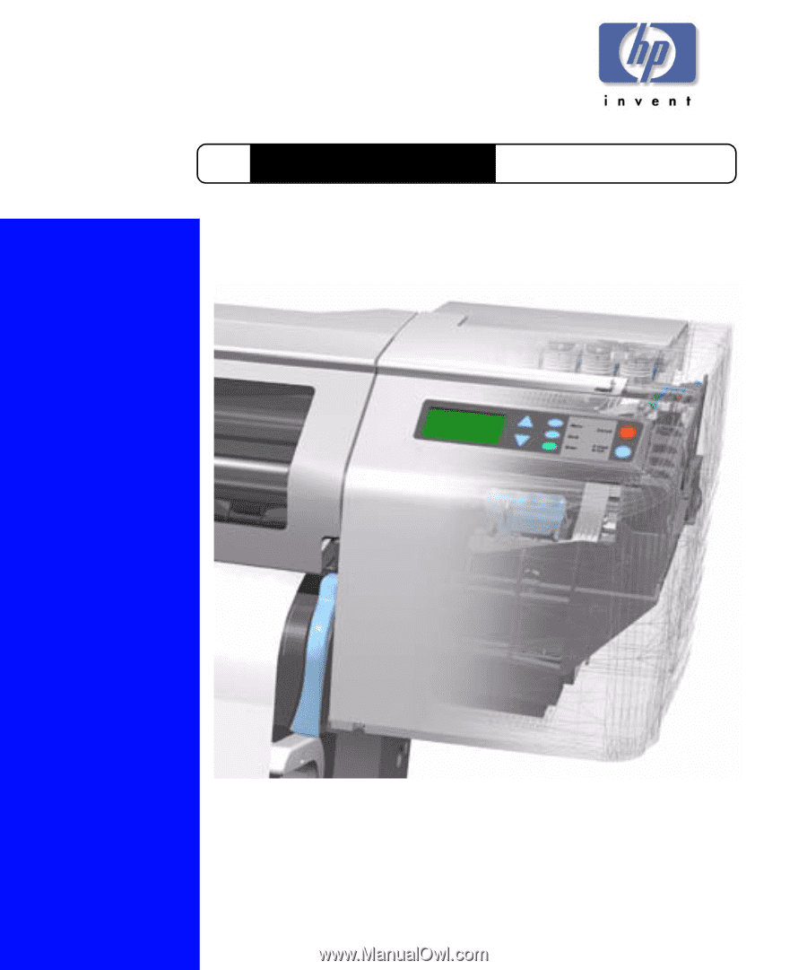
Service Manual
DesignJets 500 and 800 Series
HP
Large-Format Printers