HP C7769B Service Manual - Page 225
Remove the Right Hand Cover - Refer
 |
View all HP C7769B manuals
Add to My Manuals
Save this manual to your list of manuals |
Page 225 highlights
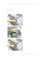
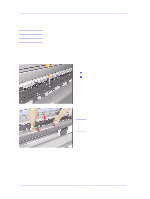
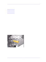
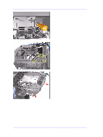
Removal and Installation Interconnect Cable Removal WARNING Switch off the printer and remove the power cord. 1. Remove the Left Hand Cover - Refer to Page 8-5. 2. Remove the Right Hand Cover - Refer to Page 8-7. 3. Remove the Electronics Module Refer to Page 8-24. 4. Remove the Left Encoder Holder Refer to Page 8-33. 5. Remove the Service Station - Refer to Page 8-52. 6. Remove the Service Station Holder Refer to Page 8-57. 7. Slide the Cable out of the Printer from the right hand side. NOTE Make sure when removing the cable that it does NOT scratch against the edge of the beam. NOTE Make sure that the Plastic Protector is NOT removed while removing the Cable. HP DesignJets 500 and 800 Series Printers Service Manual 8-59
-
 1
1 -
2
-
3
-
4
-
5
-
6
-
7
-
8
-
9
-
10
-
11
-
12
-
13
-
14
-
15
-
16
-
17
-
18
-
19
-
20
-
21
-
22
-
23
-
24
-
25
-
26
-
27
-
28
-
29
-
30
-
31
-
32
-
33
-
34
-
35
-
36
-
37
-
38
-
39
-
40
-
41
-
42
-
43
-
44
-
45
-
46
-
47
-
48
-
49
-
50
-
51
-
52
-
53
-
54
-
55
-
56
-
57
-
58
-
59
-
60
-
61
-
62
-
63
-
64
-
65
-
66
-
67
-
68
-
69
-
70
-
71
-
72
-
73
-
74
-
75
-
76
-
77
-
78
-
79
-
80
-
81
-
82
-
83
-
84
-
85
-
86
-
87
-
88
-
89
-
90
-
91
-
92
-
93
-
94
-
95
-
96
-
97
-
98
-
99
-
100
-
101
-
102
-
103
-
104
-
105
-
106
-
107
-
108
-
109
-
110
-
111
-
112
-
113
-
114
-
115
-
116
-
117
-
118
-
119
-
120
-
121
-
122
-
123
-
124
-
125
-
126
-
127
-
128
-
129
-
130
-
131
-
132
-
133
-
134
-
135
-
136
-
137
-
138
-
139
-
140
-
141
-
142
-
143
-
144
-
145
-
146
-
147
-
148
-
149
-
150
-
151
-
152
-
153
-
154
-
155
-
156
-
157
-
158
-
159
-
160
-
161
-
162
-
163
-
164
-
165
-
166
-
167
-
168
-
169
-
170
-
171
-
172
-
173
-
174
-
175
-
176
-
177
-
178
-
179
-
180
-
181
-
182
-
183
-
184
-
185
-
186
-
187
-
188
-
189
-
190
-
191
-
192
-
193
-
194
-
195
-
196
-
197
-
198
-
199
-
200
-
201
-
202
-
203
-
204
-
205
-
206
-
207
-
208
-
209
-
210
-
211
-
212
-
213
-
214
-
215
-
216
-
217
-
218
-
219
-
 220
220 -
 221
221 -
 222
222 -
 223
223 -
 224
224 -
 225
225 -
 226
226 -
 227
227 -
 228
228 -
 229
229 -
 230
230 -
231
-
232
-
233
-
234
-
235
-
236
-
237
-
238
-
239
-
240
-
241
-
242
-
243
-
244
-
245
-
246
-
247
-
248
-
249
-
250
-
251
-
252
-
253
-
254
-
255
-
256
-
257
-
258
-
259
-
260
-
261
-
262
-
263
-
264
-
265
-
266
-
267
-
268
-
269
-
270
-
271
-
272
-
273
-
274
-
275
-
276
-
277
-
278
-
279
-
280
-
281
-
282
-
283
-
284
-
285
-
286
 |
 |
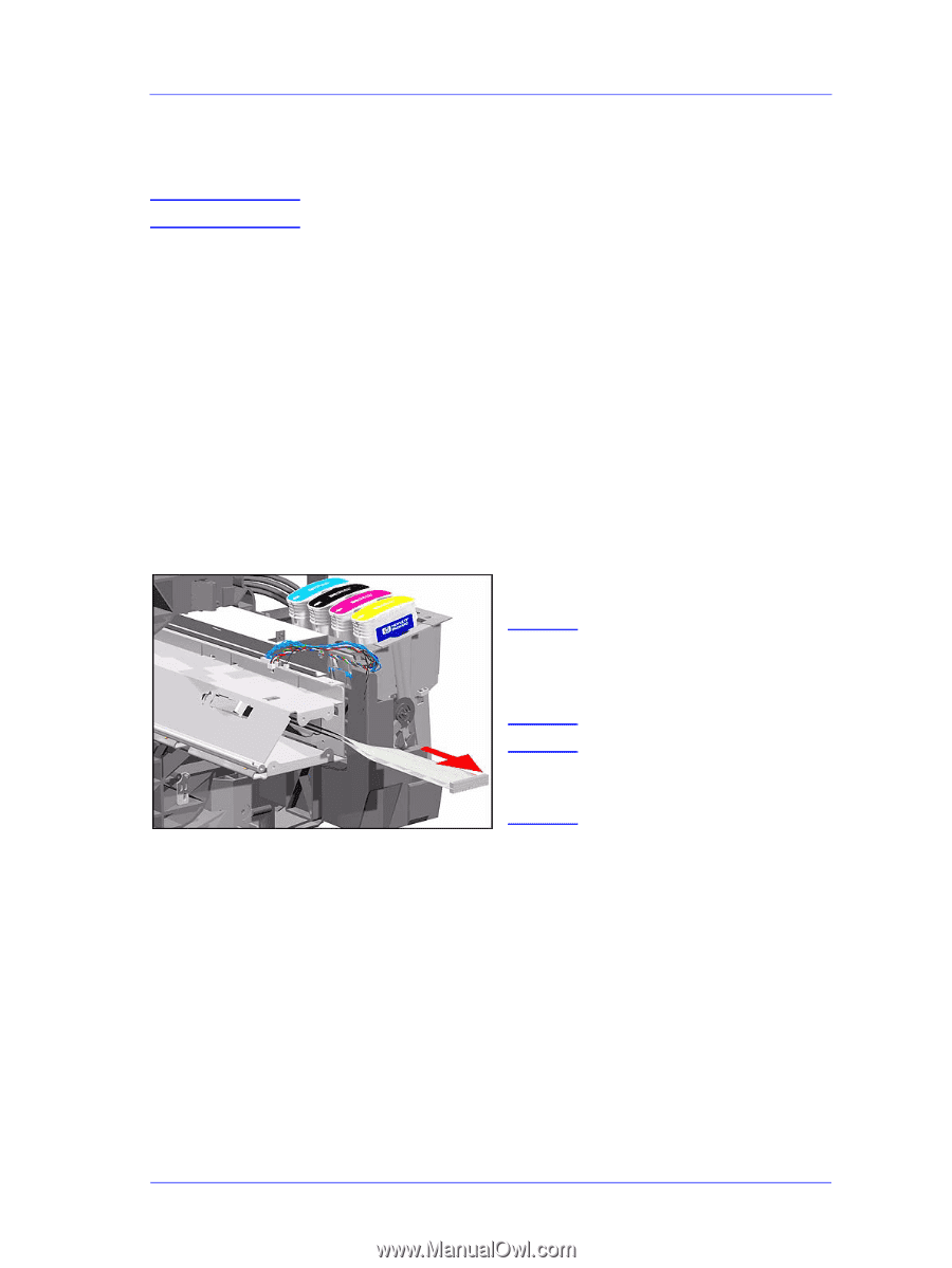
Removal and Installation
8-59
HP DesignJets 500 and 800 Series Printers Service Manual
Interconnect Cable
Removal
WARNING
Switch off the printer and remove the power cord.
1.
Remove the Left Hand Cover - Refer
to Page
8-5
.
2.
Remove the Right Hand Cover - Refer
to Page
8-7
.
3.
Remove the Electronics Module -
Refer to Page
8-24
.
4.
Remove the Left Encoder Holder -
Refer to Page
8-33
.
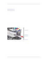
5.
Remove the Service Station - Refer to
Page
8-52
.
6.
Remove the Service Station Holder -
Refer to Page
8-57
.
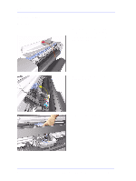
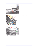
7.
Slide the Cable out of the Printer from
the right hand side.
NOTE
Make sure when removing
the cable that it does NOT
scratch against the edge of
the beam.
NOTE
Make sure that the Plastic
Protector is NOT removed
while removing the Cable.