HP C7769B Service Manual - Page 252

Remove the Front Panel - Refer

Page 252 highlights

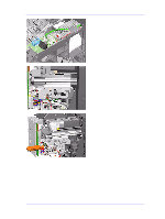
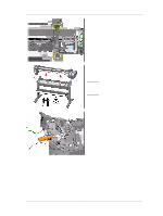
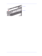
Removal and Installation Drive Roller Removal WARNING Switch off the printer and remove the power cord. 1. Remove the Spindle. 2. Remove the Left Hand Cover - Refer to Page 8-5. 3. Remove the Right Hand Cover - Refer to Page 8-7. 4. Remove the Left and Right Trims. 5. Remove the Front Panel - Refer to Page 8-9. 6. Remove the Top Cover and Window Refer to Page 8-10. 7. Remove all the Media Deflectors Refer to Page 8-11. 8. Remove the Back Platen (make sure the Lever is in the UP position) Refer to Page 8-17. 9. Remove the Media Sensor - Refer to Page 8-19. 10. Remove the Spittoon - Refer to Page 8-23. 11. Remove the Cutter Assembly - Refer to Page 8-32. 12. Remove the Cutter Guide Bracket Refer to Page 8-36. 13. Remove the Drive Roller Encoder Sensor - Refer to Page 8-38. 14. Remove the Ink Supply Station Refer to Page 8-48. 15. Remove the Cutter Guide - Refer to Page 8-55. 8-86 HP DesignJets 500 and 800 Series Printers Service Manual

  • 1
  • 2
  • 3
  • 4
  • 5
  • 6
  • 7
  • 8
  • 9
  • 10
  • 11
  • 12
  • 13
  • 14
  • 15
  • 16
  • 17
  • 18
  • 19
  • 20
  • 21
  • 22
  • 23
  • 24
  • 25
  • 26
  • 27
  • 28
  • 29
  • 30
  • 31
  • 32
  • 33
  • 34
  • 35
  • 36
  • 37
  • 38
  • 39
  • 40
  • 41
  • 42
  • 43
  • 44
  • 45
  • 46
  • 47
  • 48
  • 49
  • 50
  • 51
  • 52
  • 53
  • 54
  • 55
  • 56
  • 57
  • 58
  • 59
  • 60
  • 61
  • 62
  • 63
  • 64
  • 65
  • 66
  • 67
  • 68
  • 69
  • 70
  • 71
  • 72
  • 73
  • 74
  • 75
  • 76
  • 77
  • 78
  • 79
  • 80
  • 81
  • 82
  • 83
  • 84
  • 85
  • 86
  • 87
  • 88
  • 89
  • 90
  • 91
  • 92
  • 93
  • 94
  • 95
  • 96
  • 97
  • 98
  • 99
  • 100
  • 101
  • 102
  • 103
  • 104
  • 105
  • 106
  • 107
  • 108
  • 109
  • 110
  • 111
  • 112
  • 113
  • 114
  • 115
  • 116
  • 117
  • 118
  • 119
  • 120
  • 121
  • 122
  • 123
  • 124
  • 125
  • 126
  • 127
  • 128
  • 129
  • 130
  • 131
  • 132
  • 133
  • 134
  • 135
  • 136
  • 137
  • 138
  • 139
  • 140
  • 141
  • 142
  • 143
  • 144
  • 145
  • 146
  • 147
  • 148
  • 149
  • 150
  • 151
  • 152
  • 153
  • 154
  • 155
  • 156
  • 157
  • 158
  • 159
  • 160
  • 161
  • 162
  • 163
  • 164
  • 165
  • 166
  • 167
  • 168
  • 169
  • 170
  • 171
  • 172
  • 173
  • 174
  • 175
  • 176
  • 177
  • 178
  • 179
  • 180
  • 181
  • 182
  • 183
  • 184
  • 185
  • 186
  • 187
  • 188
  • 189
  • 190
  • 191
  • 192
  • 193
  • 194
  • 195
  • 196
  • 197
  • 198
  • 199
  • 200
  • 201
  • 202
  • 203
  • 204
  • 205
  • 206
  • 207
  • 208
  • 209
  • 210
  • 211
  • 212
  • 213
  • 214
  • 215
  • 216
  • 217
  • 218
  • 219
  • 220
  • 221
  • 222
  • 223
  • 224
  • 225
  • 226
  • 227
  • 228
  • 229
  • 230
  • 231
  • 232
  • 233
  • 234
  • 235
  • 236
  • 237
  • 238
  • 239
  • 240
  • 241
  • 242
  • 243
  • 244
  • 245
  • 246
  • 247
  • 248
  • 249
  • 250
  • 251
  • 252
  • 253
  • 254
  • 255
  • 256
  • 257
  • 258
  • 259
  • 260
  • 261
  • 262
  • 263
  • 264
  • 265
  • 266
  • 267
  • 268
  • 269
  • 270
  • 271
  • 272
  • 273
  • 274
  • 275
  • 276
  • 277
  • 278
  • 279
  • 280
  • 281
  • 282
  • 283
  • 284
  • 285
  • 286

Removal and Installation
8-86
HP DesignJets 500 and 800 Series Printers Service Manual
Drive Roller
Removal
WARNING
Switch off the printer and remove the power cord.
1.
Remove the Spindle.
2.
Remove the Left Hand Cover - Refer
to Page
8-5
.
3.
Remove the Right Hand Cover - Refer
to Page
8-7
.
4.
Remove the Left and Right Trims.
5.
Remove the Front Panel - Refer to
Page
8-9
.
6.
Remove the Top Cover and Window -
Refer to Page
8-10
.
7.
Remove all the Media Deflectors -
Refer to Page
8-11
.
8.
Remove the Back Platen (make sure
the Lever is in the UP position) -
Refer to Page
8-17
.
9.
Remove the Media Sensor - Refer to
Page
8-19
.
10.
Remove the Spittoon - Refer to Page
8-23
.
11.
Remove the Cutter Assembly - Refer
to Page
8-32
.
12.
Remove the Cutter Guide Bracket -
Refer to Page
8-36
.
13.
Remove the Drive Roller Encoder
Sensor - Refer to Page
8-38
.
14.
Remove the Ink Supply Station -
Refer to Page
8-48
.
15.
Remove the Cutter Guide - Refer to
Page
8-55
.