HP C7769B Service Manual - Page 270
The Front Panel is connected to the Interconnect PCA and NOT, As explained earlier
 |
View all HP C7769B manuals
Add to My Manuals
Save this manual to your list of manuals |
Page 270 highlights
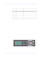
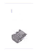
Functional Overview As explained earlier, the Power Supply provides +5.0V, +3.3V, +12V and +32V to the Main PCA with the following maximum output currents: Voltage Maximum Output Current (A) Systems +3.3V 8.0 Digital Logic & EIO cards +5.0V 1.7 Sensors, Front Panel, Bitronics and some analog logic in Main PCA +12.0V 0.45 Aerosol & Cooling fans and to generate the 5.0V going to the carriage +32.0V 3.7 Motors, Vacuum Fan and carriage Front Panel The user can interact with the printer in two ways: from the host via the I/O channels or directly via the front panel. The Front Panel is used to display messages (like the status of the machine or warnings), to configure the printer and to send commands to it (cancel the job or print a demo for example). The Front Panel has an LCD display, 7 keys (no LEDs) and a buzzer (to provide audible feedback to the user). The front panel display is a 128 x 64 pixel graphic LCD. Every pixel can be activated individually and the controller present on the Front Panel board allows it to display both text and graphics at the same time. The Front Panel has a positive reflective type display to improve its viewing characteristics and does NOT have an LED backlight. The Front Panel is connected to the Interconnect PCA and NOT directly to the Main PCA. 10-6 HP DesignJets 500 and 800 Series Printers Service Manual
-
 1
1 -
2
-
3
-
4
-
5
-
6
-
7
-
8
-
9
-
10
-
11
-
12
-
13
-
14
-
15
-
16
-
17
-
18
-
19
-
20
-
21
-
22
-
23
-
24
-
25
-
26
-
27
-
28
-
29
-
30
-
31
-
32
-
33
-
34
-
35
-
36
-
37
-
38
-
39
-
40
-
41
-
42
-
43
-
44
-
45
-
46
-
47
-
48
-
49
-
50
-
51
-
52
-
53
-
54
-
55
-
56
-
57
-
58
-
59
-
60
-
61
-
62
-
63
-
64
-
65
-
66
-
67
-
68
-
69
-
70
-
71
-
72
-
73
-
74
-
75
-
76
-
77
-
78
-
79
-
80
-
81
-
82
-
83
-
84
-
85
-
86
-
87
-
88
-
89
-
90
-
91
-
92
-
93
-
94
-
95
-
96
-
97
-
98
-
99
-
100
-
101
-
102
-
103
-
104
-
105
-
106
-
107
-
108
-
109
-
110
-
111
-
112
-
113
-
114
-
115
-
116
-
117
-
118
-
119
-
120
-
121
-
122
-
123
-
124
-
125
-
126
-
127
-
128
-
129
-
130
-
131
-
132
-
133
-
134
-
135
-
136
-
137
-
138
-
139
-
140
-
141
-
142
-
143
-
144
-
145
-
146
-
147
-
148
-
149
-
150
-
151
-
152
-
153
-
154
-
155
-
156
-
157
-
158
-
159
-
160
-
161
-
162
-
163
-
164
-
165
-
166
-
167
-
168
-
169
-
170
-
171
-
172
-
173
-
174
-
175
-
176
-
177
-
178
-
179
-
180
-
181
-
182
-
183
-
184
-
185
-
186
-
187
-
188
-
189
-
190
-
191
-
192
-
193
-
194
-
195
-
196
-
197
-
198
-
199
-
200
-
201
-
202
-
203
-
204
-
205
-
206
-
207
-
208
-
209
-
210
-
211
-
212
-
213
-
214
-
215
-
216
-
217
-
218
-
219
-
220
-
221
-
222
-
223
-
224
-
225
-
226
-
227
-
228
-
229
-
230
-
231
-
232
-
233
-
234
-
235
-
236
-
237
-
238
-
239
-
240
-
241
-
242
-
243
-
244
-
245
-
246
-
247
-
248
-
249
-
250
-
251
-
252
-
253
-
254
-
255
-
256
-
257
-
258
-
259
-
260
-
261
-
262
-
263
-
264
-
 265
265 -
 266
266 -
 267
267 -
 268
268 -
 269
269 -
 270
270 -
 271
271 -
 272
272 -
 273
273 -
 274
274 -
 275
275 -
276
-
277
-
278
-
279
-
280
-
281
-
282
-
283
-
284
-
285
-
286
 |
 |
