Kyocera FS 3830N FS-3820N/3830N Operation Guide Rev-1.1 - Page 210
Serial Interface (Option), RS-232C Interface
 |
View all Kyocera FS 3830N manuals
Add to My Manuals
Save this manual to your list of manuals |
Page 210 highlights
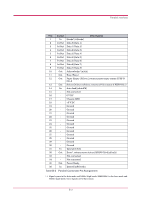
Serial Interface (Option) Serial Interface (Option) Installing the option serial interface board kit (IB-11) in the printer enables connection to a computer with an RS-232C standard serial interface. RS-232C Interface Interface Signals The pins of the printer's RS-232C interface connector carry the signals listed in table below. The table also indicates whether each signal is incoming or outgoing with respect to the printer. Pin 1 2 3 4 5 6 7 20 Table B-4 In/out - Out In Out In In Out Signal FG TXD RXD RTS CTS DSR SG DTR Description Frame ground Transmit Data Receive Data Request To Send Clear To Send Data Set Ready Signal Ground Data Terminal Ready Brief descriptions of the signals follow. FG - Frame Ground - (Pin 1) This pin is connected directly to the printer frame. TXD - Transmit Data - (Pin 2) This output carries asynchronous data sent by the printer to the computer. It is used mainly in handshaking protocols. RXD - Receive Data - (Pin 3) This input carries serial asynchronous data sent by the computer to the printer. RTS - Request To Send - (Pin 4) This output is always held high (above 3 volts). CTS - Clear To Send - (Pin 5) DSR - Data Set Ready - (Pin 6) Unused. B-6
-
 1
1 -
2
-
3
-
4
-
5
-
6
-
7
-
8
-
9
-
10
-
11
-
12
-
13
-
14
-
15
-
16
-
17
-
18
-
19
-
20
-
21
-
22
-
23
-
24
-
25
-
26
-
27
-
28
-
29
-
30
-
31
-
32
-
33
-
34
-
35
-
36
-
37
-
38
-
39
-
40
-
41
-
42
-
43
-
44
-
45
-
46
-
47
-
48
-
49
-
50
-
51
-
52
-
53
-
54
-
55
-
56
-
57
-
58
-
59
-
60
-
61
-
62
-
63
-
64
-
65
-
66
-
67
-
68
-
69
-
70
-
71
-
72
-
73
-
74
-
75
-
76
-
77
-
78
-
79
-
80
-
81
-
82
-
83
-
84
-
85
-
86
-
87
-
88
-
89
-
90
-
91
-
92
-
93
-
94
-
95
-
96
-
97
-
98
-
99
-
100
-
101
-
102
-
103
-
104
-
105
-
106
-
107
-
108
-
109
-
110
-
111
-
112
-
113
-
114
-
115
-
116
-
117
-
118
-
119
-
120
-
121
-
122
-
123
-
124
-
125
-
126
-
127
-
128
-
129
-
130
-
131
-
132
-
133
-
134
-
135
-
136
-
137
-
138
-
139
-
140
-
141
-
142
-
143
-
144
-
145
-
146
-
147
-
148
-
149
-
150
-
151
-
152
-
153
-
154
-
155
-
156
-
157
-
158
-
159
-
160
-
161
-
162
-
163
-
164
-
165
-
166
-
167
-
168
-
169
-
170
-
171
-
172
-
173
-
174
-
175
-
176
-
177
-
178
-
179
-
180
-
181
-
182
-
183
-
184
-
185
-
186
-
187
-
188
-
189
-
190
-
191
-
192
-
193
-
194
-
195
-
196
-
197
-
198
-
199
-
200
-
201
-
202
-
203
-
204
-
 205
205 -
 206
206 -
 207
207 -
 208
208 -
 209
209 -
 210
210 -
 211
211 -
 212
212 -
 213
213 -
 214
214 -
 215
215 -
216
-
217
-
218
-
219
-
220
-
221
-
222
-
223
-
224
-
225
-
226
-
227
 |
 |