Netgear FVS318 FVS318v3 Reference Manual - Page 158
Uplink Switches, Crossover Cables, and MDI/MDIX Switching
 |
UPC - 606449023381
View all Netgear FVS318 manuals
Add to My Manuals
Save this manual to your list of manuals |
Page 158 highlights
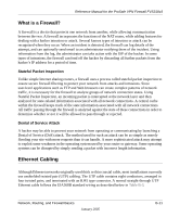
Reference Manual for the ProSafe VPN Firewall FVS318v3 Figure B-6: Category 5 UTP cable with male RJ-45 plug at each end Note: Flat "silver satin" telephone cable may have the same RJ-45 plug. However, using telephone cable results in excessive collisions, causing the attached port to be partitioned or disconnected from the network. Uplink Switches, Crossover Cables, and MDI/MDIX Switching In the wiring table above, the concept of transmit and receive are from the perspective of the PC, which is wired as Media Dependant Interface (MDI). In this wiring, the PC transmits on pins 1 and 2. At the hub, the perspective is reversed, and the hub receives on pins 1 and 2. This wiring is referred to as Media Dependant Interface - Crossover (MDI-X). When connecting a PC to a PC, or a hub port to another hub port, the transmit pair must be exchanged with the receive pair. This exchange is done by one of two mechanisms. Most hubs provide an Uplink switch which will exchange the pairs on one port, allowing that port to be connected to another hub using a normal Ethernet cable. The second method is to use a crossover cable, which is a special cable in which the transmit and receive pairs are exchanged at one of the two cable connectors. Crossover cables are often unmarked as such, and must be identified by comparing the two connectors. Since the cable connectors are clear plastic, it is easy to place them side by side and view the order of the wire colors on each. On a straight-through cable, the color order will be the same on both connectors. On a crossover cable, the orange and blue pairs will be exchanged from one connector to the other. B-14 January 2005 Network, Routing, and Firewall Basics
-
 1
1 -
2
-
3
-
4
-
5
-
6
-
7
-
8
-
9
-
10
-
11
-
12
-
13
-
14
-
15
-
16
-
17
-
18
-
19
-
20
-
21
-
22
-
23
-
24
-
25
-
26
-
27
-
28
-
29
-
30
-
31
-
32
-
33
-
34
-
35
-
36
-
37
-
38
-
39
-
40
-
41
-
42
-
43
-
44
-
45
-
46
-
47
-
48
-
49
-
50
-
51
-
52
-
53
-
54
-
55
-
56
-
57
-
58
-
59
-
60
-
61
-
62
-
63
-
64
-
65
-
66
-
67
-
68
-
69
-
70
-
71
-
72
-
73
-
74
-
75
-
76
-
77
-
78
-
79
-
80
-
81
-
82
-
83
-
84
-
85
-
86
-
87
-
88
-
89
-
90
-
91
-
92
-
93
-
94
-
95
-
96
-
97
-
98
-
99
-
100
-
101
-
102
-
103
-
104
-
105
-
106
-
107
-
108
-
109
-
110
-
111
-
112
-
113
-
114
-
115
-
116
-
117
-
118
-
119
-
120
-
121
-
122
-
123
-
124
-
125
-
126
-
127
-
128
-
129
-
130
-
131
-
132
-
133
-
134
-
135
-
136
-
137
-
138
-
139
-
140
-
141
-
142
-
143
-
144
-
145
-
146
-
147
-
148
-
149
-
150
-
151
-
152
-
 153
153 -
 154
154 -
 155
155 -
 156
156 -
 157
157 -
 158
158 -
 159
159 -
 160
160 -
 161
161 -
 162
162 -
 163
163 -
164
-
165
-
166
-
167
-
168
-
169
-
170
-
171
-
172
-
173
-
174
-
175
-
176
-
177
-
178
-
179
-
180
-
181
-
182
-
183
-
184
-
185
-
186
-
187
-
188
-
189
-
190
-
191
-
192
-
193
-
194
-
195
-
196
-
197
-
198
-
199
-
200
-
201
-
202
-
203
-
204
-
205
-
206
-
207
-
208
-
209
-
210
-
211
-
212
-
213
-
214
-
215
-
216
-
217
-
218
-
219
-
220
-
221
-
222
-
223
-
224
-
225
-
226
-
227
-
228
-
229
-
230
-
231
-
232
-
233
-
234
-
235
-
236
-
237
-
238
-
239
-
240
-
241
-
242
 |
 |
