Netgear FVS318 FVS318v3 Reference Manual - Page 76
How to Set Up a Gateway-to-Gateway VPN Configuration, Table 5-1 on Advanced
 |
UPC - 606449023381
View all Netgear FVS318 manuals
Add to My Manuals
Save this manual to your list of manuals |
Page 76 highlights
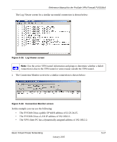
Reference Manual for the ProSafe VPN Firewall FVS318v3 How to Set Up a Gateway-to-Gateway VPN Configuration Note: This section uses the VPN Wizard to set up the VPN tunnel using the VPNC default parameters listed in Table 5-1 on page 5-4. If you have special requirements not covered by these VPNC-recommended parameters, refer to Chapter 6, "Advanced Virtual Private Networking" to set up the VPN tunnel. A FVS318v3 VPN Firewall VPN Tunnel B FVS318v3 VPN Firewall PCs PCs Figure 5-22: Gateway-to-Gateway VPN Tunnel Follow the procedure below to set the LAN IPs on each FVS318v3 to different subnets and configure each properly for the Internet. The LAN IP address ranges of each VPN endpoint must be different. The connection will fail if both are using the NETGEAR default address range of 192.168.0.x. In this example, LAN A uses 192.168.0.1 and LAN B uses 192.168.3.1. 5-20 January 2005 Basic Virtual Private Networking
-
 1
1 -
2
-
3
-
4
-
5
-
6
-
7
-
8
-
9
-
10
-
11
-
12
-
13
-
14
-
15
-
16
-
17
-
18
-
19
-
20
-
21
-
22
-
23
-
24
-
25
-
26
-
27
-
28
-
29
-
30
-
31
-
32
-
33
-
34
-
35
-
36
-
37
-
38
-
39
-
40
-
41
-
42
-
43
-
44
-
45
-
46
-
47
-
48
-
49
-
50
-
51
-
52
-
53
-
54
-
55
-
56
-
57
-
58
-
59
-
60
-
61
-
62
-
63
-
64
-
65
-
66
-
67
-
68
-
69
-
70
-
 71
71 -
 72
72 -
 73
73 -
 74
74 -
 75
75 -
 76
76 -
 77
77 -
 78
78 -
 79
79 -
 80
80 -
 81
81 -
82
-
83
-
84
-
85
-
86
-
87
-
88
-
89
-
90
-
91
-
92
-
93
-
94
-
95
-
96
-
97
-
98
-
99
-
100
-
101
-
102
-
103
-
104
-
105
-
106
-
107
-
108
-
109
-
110
-
111
-
112
-
113
-
114
-
115
-
116
-
117
-
118
-
119
-
120
-
121
-
122
-
123
-
124
-
125
-
126
-
127
-
128
-
129
-
130
-
131
-
132
-
133
-
134
-
135
-
136
-
137
-
138
-
139
-
140
-
141
-
142
-
143
-
144
-
145
-
146
-
147
-
148
-
149
-
150
-
151
-
152
-
153
-
154
-
155
-
156
-
157
-
158
-
159
-
160
-
161
-
162
-
163
-
164
-
165
-
166
-
167
-
168
-
169
-
170
-
171
-
172
-
173
-
174
-
175
-
176
-
177
-
178
-
179
-
180
-
181
-
182
-
183
-
184
-
185
-
186
-
187
-
188
-
189
-
190
-
191
-
192
-
193
-
194
-
195
-
196
-
197
-
198
-
199
-
200
-
201
-
202
-
203
-
204
-
205
-
206
-
207
-
208
-
209
-
210
-
211
-
212
-
213
-
214
-
215
-
216
-
217
-
218
-
219
-
220
-
221
-
222
-
223
-
224
-
225
-
226
-
227
-
228
-
229
-
230
-
231
-
232
-
233
-
234
-
235
-
236
-
237
-
238
-
239
-
240
-
241
-
242
 |
 |
