Nokia IP1220 Installation Guide - Page 20
Ethernet Management Ports, IP1220 and IP1260 Security Platforms Installation Guide, - hard drive
 |
View all Nokia IP1220 manuals
Add to My Manuals
Save this manual to your list of manuals |
Page 20 highlights
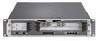
1 Overview Figure 1 Component Locations Front View System status LEDs Dual 6U PMC carrier or ADP module expansion slots 1 and 2 hard-disk drive A hard-disk drive B Console port Grounding plug Serial (AUX) port PCMCIA slots 00307a.3 Ethernet management ports (slot 3) Ethernet Management Ports The Ethernet management ports are located in slot 3. Figure 2 shows the layout of the Ethernet management ports and link LEDs. The top link LED represents the left-most port (port 1). The remaining LEDs represent the remaining ports from top to bottom and left to right. Note The Ethernet management ports are intended for management purposes. These ports do not provide the same performance as Ethernet cards in the PMC slots. Figure 2 Ethernet Management Ports Details LInk LEDs (green) Port 1 Port 2 Port 3 Port 4 RJ-45 connectors 00120a Caution Cables that connect to the Ethernet NIC must be IEEE 802.3 compliant to prevent potential data loss. 20 IP1220 and IP1260 Security Platforms Installation Guide
-
 1
1 -
2
-
3
-
4
-
5
-
6
-
7
-
8
-
9
-
10
-
11
-
12
-
13
-
14
-
 15
15 -
 16
16 -
 17
17 -
 18
18 -
 19
19 -
 20
20 -
 21
21 -
 22
22 -
 23
23 -
 24
24 -
 25
25 -
26
-
27
-
28
-
29
-
30
-
31
-
32
-
33
-
34
-
35
-
36
-
37
-
38
-
39
-
40
-
41
-
42
-
43
-
44
-
45
-
46
-
47
-
48
-
49
-
50
-
51
-
52
-
53
-
54
-
55
-
56
-
57
-
58
-
59
-
60
-
61
-
62
-
63
-
64
-
65
-
66
-
67
-
68
-
69
-
70
-
71
-
72
-
73
-
74
-
75
-
76
-
77
-
78
-
79
-
80
-
81
-
82
-
83
-
84
-
85
-
86
-
87
-
88
-
89
-
90
-
91
-
92
-
93
-
94
-
95
-
96
-
97
-
98
-
99
-
100
-
101
-
102
-
103
-
104
-
105
-
106
-
107
-
108
-
109
-
110
-
111
-
112
-
113
-
114
-
115
-
116
-
117
-
118
-
119
-
120
-
121
-
122
-
123
-
124
-
125
-
126
-
127
-
128
 |
 |
