Oki ML490 Maintenance Manual
Oki ML490 Manual
 |
View all Oki ML490 manuals
Add to My Manuals
Save this manual to your list of manuals |
Oki ML490 manual content summary:
- Oki ML490 | Maintenance Manual - Page 1
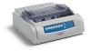
ML490/491 PRINTER Maintenance Manual ODA 42114101 Rev.1 1 / 135 - Oki ML490 | Maintenance Manual - Page 2
42114101 Rev.1 2 / - Oki ML490 | Maintenance Manual - Page 3
describes how to maintain the ML490/491 printer in the field. This manual is for customer engineers. For further information, refer to the Users Manual for handling or operating the equipment. The relation between the destination point and the model name of this printer is as follows. For ODA - Oki ML490 | Maintenance Manual - Page 4
(continuous paper 53 3. ASSEMBLY/DISASSEMBLY 54 3.1 Precaution for Parts Replacement 54 3.2 Service Tools ...55 3.3 Disassembly/Reassembly Procedure 56 3.3.1 Printhead ...58 3.3.2 Ribbon Protector 59 3.3.3 Pull-up Roller Assy 60 3.3.4 Upper Cover Assy, Access Cover Assy and Sheet Guide Assy - Oki ML490 | Maintenance Manual - Page 5
Table ...97 6.3 Lamp Display ...98 6.4 Connection Circuit Check for Printhead and SP/LF Motor 102 6.5 Troubleshooting flow chart 104 APPENDIX A PCB LAYOUT 116 APPENDIX B SPARE PARTS LIST 117 APPENDIX C RS-232C SERIAL INTERFACE BOARD (OPTION 128 1. GENERAL ...128 2. OPERATION DESCRIPTION 128 - Oki ML490 | Maintenance Manual - Page 6
1. CONFIGURATION 1.1 Standard Printer Configuration This printer consists of the following assemblies: Sheet guide assy Platen knob Access cover assy Power supply board Control board Upper cover Transformer assy Pull-up roller assy Operation panel assy Main chassis assy - Oki ML490 | Maintenance Manual - Page 7
1.2 Options (1) Cut sheet feeder unit (CSF) (Narrow and wide versions available) Dual-bin CSF Single-bin CSF Attachment assy Attachment assy (2) Pull-tractor assy 42114101 Rev.1 7 / - Oki ML490 | Maintenance Manual - Page 8
(3) Bottom push tractor unit (4) Roll paper stand (Narrow only) (5) RS232C Serial interface board 42114101 Rev.1 8 / - Oki ML490 | Maintenance Manual - Page 9
The power to other electrical parts is also distributed through the connectors core, all OKI original architecture. The processor has a 20 bit address bus and a 16 bit data bus. mechanism for the entire printer by executing the control program through the LSI and driver circuits. 42114101 Rev.1 - Oki ML490 | Maintenance Manual - Page 10
SPTEMP ROM 8Mbit Max. 16Mbit Serial Serial EEPROM 1Kbits I/F-IPT Print-IPT Release-SW Bottom-SW M FAN DRAM 4Mbit PE-SENSOR .) CSF (opt.) Roll paper stand ParaI/F HTEMP Head driver (opt.) Serial- I/F HEAD HD alarm HEADGAP HEADGAP-SW Photo sensor SP/LF driver M SP Thermister SPTEMP M - Oki ML490 | Maintenance Manual - Page 11
(2) Program ROM This is a 512K × 16 bits (8M bit) [MAX 16M bit] OTPROM or MASK ROM with the control program for the printer stored. The MPU executes instructions under this program. The program ROM is assigned to the program memory area of the MPU and is fetched by the PSEN-N signal of the - Oki ML490 | Maintenance Manual - Page 12
× 16-bit (4M bit), and used as buffers (such as receiving buffer, printing buffer, DLL buffer and working buffer). The following shows the examples of the memory WR-N D0~D15 (Write) 16-bit bus, Word instruction * Clockout is provided when the original excitation is selected. 42114101 Rev.1 12 / - Oki ML490 | Maintenance Manual - Page 13
(4) USB Controller The USB Controller detects and controls the USB interfacee. The following shows the USB Controller access operation. MPU PP0O2 2 RD PWSRELN Clockout * A0~A7 USBCS-N RD-N A0~A7 D0~D7 USBCS-N RD-N WRL-N USB Controller CE RD WR D0~D7 (Read) WRL-N D0~D7 (Write) * Clockout is - Oki ML490 | Maintenance Manual - Page 14
(5) EEPROM The EEPROM is a CMOS serial I/O type memory which is capable of electrically erasing and writing 1,024 bits. The EEPROM contains menu data. The following shows the memory access operation. MPU EEPROM EEDIN-P P24 D1 EECS-P P27 CS ; ; EEDOUT-P P25 DO EECLK-P P26 SK PRE = O PE - Oki ML490 | Maintenance Manual - Page 15
-N WRL-N LSICS-N ALE ALE RDN WRL LSIC RAS 1 RAS 0 RAS-N Clockout* A0~A19 LSICS-N ALE D0~D7 (Read) RD-N D0~D7 (Write) WRL-N Address Address Data Data * Clockout is provided when the original excitation is selected. 42114101 Rev.1 15 / - Oki ML490 | Maintenance Manual - Page 16
2.1.3 Initialization This printer is initialized when the power is turned on or when the -N. Reset operation by I-PRIME starts program to initialize, but does not reset the MPU. The program here sets the mode of the LSI including the MPU, checks the memories (ROMs and RAMs), then carries out carriage - Oki ML490 | Maintenance Manual - Page 17
outputs the RXD signal to inform the MPU of data reception. The data is read upon receiving the RD-N signal from the MPU. When the data processing ends, the BUSY signal is set to off and the ACK-N signal in sent to request the next data. When reception is impossible because the buffer is full - Oki ML490 | Maintenance Manual - Page 18
Bus (USB) Universal Serial Bus Specification Revision 1.0 compliance. 1) Connector • Printer Side • Cable Side : "B" Receptacle (Upstream Input to the USB 3 4 5) Mode & Class of Device • Full - speed Driver • Self - powered Device 6) Data Signaling Rate • Full - speed function - 12Mb/s ± 0.25 - Oki ML490 | Maintenance Manual - Page 19
9) Signal Level • Input / Output Level Parameter Symbol Min. Input Levels : High (driven) VIH 2.0 High (floating) VIHZ 2.7 Low VIL Output Levels : Low OL 0.0 High (driven) OH 2.8 Output Signal Crossover Voltage VCRS 1.3 Max. Units V 3.6 V 0.8 V 0.3 V 3.6 V 2.0 V - Oki ML490 | Maintenance Manual - Page 20
2.1.5 Print Control Print data is transmitted as parallel data (HEAD1~HEAD24) from LSI to print head. LSI generates print timing and drive time. Control Board MPU LSI A/D bus Print Data DRIVER Print Data Print Head HEAD1-N~ HEAD9-N HEAD1~ HEAD9 HEAD DRIVE TIMING CHART DT1 DT2 HEAD DRIVE - Oki ML490 | Maintenance Manual - Page 21
as shown below: (a) Voltage compensation (See 2.1.8 "Alarm Circuit.") (b) Temperature compensation (See 2.1.8 "Alarm Circuit.") (c) Pin stroke compensation Platen Pin 1~4 5~20 21~24 Print Head As shown in the drawing left, the stroke length up to the platen is different for each pin. Pin coil - Oki ML490 | Maintenance Manual - Page 22
2.1.6 SP/LF Motor Control The MPU transmits serially the SP motor data and the LF motor control data too the SP/LF motor driver, according to the commands sent from the MPU. LSI MPU φA/φB P23 SPU SPV SPW SLATCH-N P20 SDATA-N P22 SCLK-N MHM2025 SPU SPV SPW SP Decoder - Oki ML490 | Maintenance Manual - Page 23
driver (MHM2025) drives the three-phase brushless motor based on the phase signal (SPU, SPV and SPW) from the LSI and the speed instruction data from comparing the target speed for each print mode with the actual current speed to change the speed instruction data, the motor speed is accelerated or - Oki ML490 | Maintenance Manual - Page 24
. The LSI divides these edge pulse signals in accordance with the print pitch, and sends the IPT signal to provide dot-on timing motor driver (MHM2025) drives the LF motor in two-phase or 1-2 phase bipolar, based on the phase changeover data and the output current data from the MPU. The data from - Oki ML490 | Maintenance Manual - Page 25
panel control IC. LSI OPTD OPCK NPA2 OPRD OPTXD 48 OPCLK 47 OPCLR-N 45 OPRXD 46 Operation panel control IC Command and Data latch LED driver +5V Switch controller A 2-byte (15 bits + 1 even parity bit) command (OPTXD) is transmitted to the Operation panel contol IC in synchronization with - Oki ML490 | Maintenance Manual - Page 26
, 2 etc. OPRXD OPCLR-N bit0 bit7 Command response (first) Note Command response (second) Read instruction for 3 data read Response check for OK or NG YES 5 6 4 NO Error notification Instruction for retransmission Reset within IC 7 8 Note: From the illustration above, you can see that - Oki ML490 | Maintenance Manual - Page 27
) by R753 and R524 and input into the A/D port of the MPU to control the drive time and the print speed (pass number) of the head. +50V R753 POWLEV R524 (a) Head drive time The head drive time is lengthened to compensate for the amount of voltage drop by monitoring the POWLEV signal once every - Oki ML490 | Maintenance Manual - Page 28
of the thermistors, one of which is contained in the print head and the other in the SP/LF driver, is monitored by the A/D port of the MPU to control the voltage. Temp Stop Mode up Mode down 132°C 122°C 118°C Mode and print control • Mixing Image and Characters Mode 1 2 3 4 5 6 7 DUTY 100% 87 - Oki ML490 | Maintenance Manual - Page 29
which is contained in the SP Motor, is monitored by the A/D port of the MPU to control the voltage. Temp Stop 105°C 95°C Mode and print control Mode 1 2 3 Temp ~ 94°C 95°C ~ 104°C 105°C ∼ PrintSpeed 100% 50% ~ 95% Stop • When the temperature exceeds 105 - Oki ML490 | Maintenance Manual - Page 30
2.1.9 Power Supply Circuit This power supply circuit supplies the +3.3VDC, +5VDC, +12VDC, +42VDC, +50VDC and -8VDC. SW Noise filter AC Fuse circuit Transformer Power supply board Rectifier +50V Rectifier +12V Regulation Circuit Converter +5V Converter +50V Converter Control board -8V - Oki ML490 | Maintenance Manual - Page 31
the head pins View from the tip of the printhead (1) The printhead configuration: The printhead is composed of the following parts: (a) Wire guide (b) Spring assembly (Wire, Armature, Spring, Yoke, Spacer) (c) Magnet assembly (Magnet, core, coil, Yoke) (d) Printed - Oki ML490 | Maintenance Manual - Page 32
from the tip of the wire guide, strikes the paper through the ribbon and prints a dot on the paper. (c) After the character has been printed, the armature is magnetically attracted again and the print wires are again concealed under the wire guide. A thermistor in the printhead prevents burning - Oki ML490 | Maintenance Manual - Page 33
Paper Print wire Printhead Platen (1) When printing Paper Armature assembly Print wire Thermistor (2) When not printing Wire guide Yoke Spacer Magnet assembly Paper 42114101 Rev.1 Figure 2-3 33 / - Oki ML490 | Maintenance Manual - Page 34
motor with motor gear (b) Carriage frame (stationary yoke and motor driver board included) (c) Carriage shaft (d) Space rack (e) Sensor (f) Encoder by the sensor. Print Head Carriage shaft Carriage frame Space rack Encoder disk Encoder sensor Motor gear Slider Guide rail Figure 2-4 42114101 Rev - Oki ML490 | Maintenance Manual - Page 35
of the space motor PC board. The printer will reduce the printing speed automatically to ensure that adequate printing pressure is maintained for multipart paper. And, the adjusting cam adjusts the headgap toward left and right side in accordance with the guide rail up and down as a position of - Oki ML490 | Maintenance Manual - Page 36
Platen Range 1 2 3 4 5 Carriage shaft Printhead Adjusting lever Adjusting screw Idler gear Adjusting gear Range from 5 to 1 Adjusting screw Adjusting cam C.C.W. Narrows Printhead Platen Range from 1 to 5 Guide rail C.W. Widens 42114101 Rev.1 Figure 2-5 36 / - Oki ML490 | Maintenance Manual - Page 37
2-6.) The ribbon driver mechanism moves the ribbon in synchronization with the space motor operation. The ribbon drive mechanism consist of the following items: (a) Ribbon drive gear assembly (b) Ribbon gear (space motor) (c) Ribbon cartridge (1) Ribbon cartridge An endless ribbon with a single - Oki ML490 | Maintenance Manual - Page 38
Ribbon cartridge Drive gear Ink tank 42114101 Rev.1 Figure 2-6 38 / - Oki ML490 | Maintenance Manual - Page 39
feed operation Feeding of the paper is performed by turning the platen and the pin tractor, which is driven by the LF pulse motor. Item of the paper feed mechanism are as follows: (a) Pulse motor with gears (b) Decelerating gear (c) Platen (d) Tractor feed unit (e) Pressure roller 42114101 Rev - Oki ML490 | Maintenance Manual - Page 40
paper paths can be selected and set by the change lever. (a) TOP (for cut sheet) When the cut sheet is used in the manual mode or fed by the CSF (option), set the print start position after Manual/ automatic CSF: Operation SW or instruction • Operation SW or • instruction • Operation SW or • instruction - Oki ML490 | Maintenance Manual - Page 41
Control Power supply Assy Bottom switch Switch lever Rear switch Change gear shaft Change lever Release shaft Change arm Platen TOP REAR BOTTOM Change lever Tractor gear Platen gear (R) Change gear Reset spring Idle gear (Bottom tractor unit) Figure 2-7 42114101 Rev.1 41 / - Oki ML490 | Maintenance Manual - Page 42
change lever must be in the TOP position to grab the paper, while disengaging the push tractor. When the change lever is set to the TOP position, the cut sheet is automatically fed in up to the print start position after pausing for the wait time stored in the menu. Stepping motor (LF - Oki ML490 | Maintenance Manual - Page 43
idler gear and the change gear. The rotation of the tractor gear makes the pin tractor belt rotate through a sheet feeder shaft, feeding the continuous paper. Paper Platen gear Tractor gear Idle gear Figure 2-9 Change gear 42114101 Rev.1 43 / - Oki ML490 | Maintenance Manual - Page 44
at the same time. To remove slack from the sheets, set the sheets according to the following procedure when using the push and pull tractors. 1 Set the change lever to the REAR position (setting the sheets to the push tractor to feed). 2 Set the paper, which is fed in front of the platen, to the - Oki ML490 | Maintenance Manual - Page 45
(5) Pull tractor mechanism (option) (See Figure 2-11.) Bottom feed of continuous sheets is possible only when an optional pull tractor unit is installed. The rotation of the platen is transmitted to the idle gear of the pull tractor unit through the platen gear at the left end of the platen. The - Oki ML490 | Maintenance Manual - Page 46
the tractor idle gear and the tractor change gear to the tractor drive gear of the bottom push tractor, and the sheet of paper is fed in to the print start position. Platen Platen gear Change gear Idle gear Tractor change gear Tractor idle gear Tractor drive gear Figure 2-12 42114101 Rev - Oki ML490 | Maintenance Manual - Page 47
(7) Paper clamp mechanism (See Figure 2-13.) When setting the change lever to the BOTTOM , TOP or REAR position, the operation of the front release gear arm changes according to the position of the - Oki ML490 | Maintenance Manual - Page 48
TOP Release cam Platen BOTTOM Change lever Change arm REAR 42114101 Rev.1 Figure 2-13 48 / - Oki ML490 | Maintenance Manual - Page 49
detection mechanism (See Figure 2-14.) (1) Cut sheet detection When the cut sheet is inserted, the point A is pushed backward and the paper near end lever B rotates counter clockwise (CCW). At this time, the rear sensor lever rotates counterclockwise (CCW), the rear sensor lever and pulls out of - Oki ML490 | Maintenance Manual - Page 50
edge of the sheet is protected by the ribbon protector so that it can stop at a position just near to the print head (0 tear off position) to start printing at the front end of the sheet, without causing the sheet to crumple or curl up. The printing starts at the front end of the sheet - Oki ML490 | Maintenance Manual - Page 51
the print position. 4) When the default is selected, the sheet of paper is feed in up to the position 0.85 inches (first dot position) from the upper end of the sheet. However, the 0 tear off mechanism allows the printing at the front end of the sheet by changing the TOF position. Sheet setting Time - Oki ML490 | Maintenance Manual - Page 52
side position. (See Figure 2-13.) 2) Set a sheet of paper either to the push tractor. 3) Press the "FF/LOAD" switch. 4) The LF motor starts its operation to feed the paper up to the print start position. 5) The paper is fed in up to the TOF position (Factory default: 0.85 inches from the top). Push - Oki ML490 | Maintenance Manual - Page 53
button on the operation panel. 2) Reverse LF is started and paper is fed in reverse until paper end occurs or 19 inches maximum have been fed. 3) The paper is fed in reverse, to leave the paper on the push-tractor. ;PARK PE Paper end detection ;;;;LF action Reverse LF from P.E. Sensor to tractor - Oki ML490 | Maintenance Manual - Page 54
receptacle AC cable Interface cable (2) Do not disassemble the printer as long as it is operating normally. (3) Do not remove unnecessary parts, and limit the disassembly area as much as possible. (4) Use the designated service tools. (5) Carry out disassembly in the prescribed sequence; otherwise - Oki ML490 | Maintenance Manual - Page 55
Tools Table 3.1 lists the tools necessary for replacing printed circuit boards and parts of units in the field. Table 3.1 Service tools No. Service Tool Q'ty Use Remarks 1 No. 1-100 Phillips screwdriver 1 Screws 2.6 mm 2 No. 2-200 Phillips screwdriver 1 Screws 3-5 mm 3 No. 3-100 - Oki ML490 | Maintenance Manual - Page 56
This section explains the assembly replacement procedures according to the following disassembly system. [Parts Layout] Upper cover assy Transformer assy Control/Power supply board Printhead Driver board Printer unit Operation panel board Figure 3-1 Printer unit 42114101 Rev.1 56 / - Oki ML490 | Maintenance Manual - Page 57
how to change parts and assemblies appearing in the disassembly diagram below. Printer unit 3.3.1 Printhead 3.3.2 Ribbon protector 3.3.3 Pull-up roller assy 3.3.4 Upper cover, access cover and sheet guide 3.3.5 Gear case assy 3.3.6 PC connector 3.3.7 Space motor and guide roller assy 3.3.8 Space - Oki ML490 | Maintenance Manual - Page 58
between printhead 2 and carriage frame 4 as shown Figure 3-3. (3) Be sure to check the gap between platen and printhead (see 4). (4) Be careful not to touch the print head while it is very hot. (5) Make sure that there is not any dust or oil on the connector contact section A. If it is found, wipe - Oki ML490 | Maintenance Manual - Page 59
3.3.2 Ribbon Protector (1) Remove the printhead (see 3.3.1). (2) Open the pull-up roller cover 1. (3) Raise and remove the ribbon protector 2. (4) To install, follow the removal steps in the reverse order. 2 1 42114101 Rev.1 59 / - Oki ML490 | Maintenance Manual - Page 60
3.3.3 Pull-up Roller Assy (1) Open the access cover 1. (2) Lift up the sheet guide Assy 4 to remove. Note: Please do after always remaining the sheet guide Assy 4 when the pull-up roller Assy 2 is installed and removed. (3) Tilting the pull-up roller Assy 2 toward the front, remove from the shaft of - Oki ML490 | Maintenance Manual - Page 61
narrow type) of frame. (5) Raise the upper cover Assy 3 to remove. (6) Open the access cover Assy 4 toward the front to remove. (7) Lift up the sheet guide Assy 5 to remove. (8) To install, follow the removal steps in the reverse order. Remark on assembly: Match the posts A at the both sides of the - Oki ML490 | Maintenance Manual - Page 62
3.3.5 Gear Case Assy (1) Remove the printhead (see 3.31). (2) Remove the upper cover (see 3.3.4 (1) - (5)). (3) Move the carriage Assy to right hand side, remove two screws 1, then the space motor 2. (4) Disconnect a carriage cable. (5) Disengage claws (4 places). Using a flat-blade screwdriver, - Oki ML490 | Maintenance Manual - Page 63
3.3.6 PC Connector (1) Remove the printhead (see 3.3.1). (2) Remove the upper cover (see 3.3.4 (1) - (5)). (3) Remove the gear case Assy (see 3.3.5). (4) Remove the PC connector 1 from the space motor Assy 2. (5) To install, follow the removal steps in the reverse order. Note on installation: (1) Do - Oki ML490 | Maintenance Manual - Page 64
on installation: (1) Do not touch the terminals of space motor 1. Also, take care to avoid dust or foreign matters. (2) When installing the guide roller Assy 3, push portions A and B against the space motor 1. (3) When installing the space motor 1, align the face C with carriage frame 4 and push - Oki ML490 | Maintenance Manual - Page 65
3.3.8 Space Rack (1) Remove the printhead (see 3.3.1). (2) Remove the upper cover (see 3.3.4 (1) - (5)). (3) Remove the gear case Assy (see 3.3.5). (4) Remove the space motor (see 3.3.7). (5) Remove the spring 1. (6) Disengage the claw on left side of space rack 2 from the frame, and remove the - Oki ML490 | Maintenance Manual - Page 66
to fold the carriage cable 7 during installation. Curve slightly the carriage cable 7 when assembling into the fasteners. (2) Make sure that the paper end lever A will not contact the Paper end Sensor 0 when mounting the Control Board. (3) Make sure that there is not any dust or oil on the connector - Oki ML490 | Maintenance Manual - Page 67
3.3.10 Backup Roller Holder Assy (1) Remove the printhead (see 3.3.1). (2) Remove the upper cover (see 3.3.4 (1) - (5)). (3) Remove the gear case Assy (see 3.3.5). (4) Remove the space motor (see 3.3.7). (5) Remove the backup roller spring 2. Disengage claws (2 places) of roller holder from the - Oki ML490 | Maintenance Manual - Page 68
3.3.11 Platen Assy (1) Remove the printhead (see 3.3.1). (2) Remove the ribbon protector (see 3.3.2). (3) Remove the pull-up roller Assy (see 3.3.3). (4) Remove the upper cover (see 3.3.1 (1) - (5)). (5) Turn the change lever 1 to the bottom position. (6) Push in the - Oki ML490 | Maintenance Manual - Page 69
3.3.12 Control Board (TFS) (1) Remove the upper cover (see 3.3.4 (1) - (5)). (2) Remove two screws 1, and release the Control Board 2 and PCB sheet 5 by lifting clamp 4. (3) Disconnect all cables from Control Board 2. (4) To install, follow the removal steps in the reverse order. Note on - Oki ML490 | Maintenance Manual - Page 70
Motor (1) Remove the printhead (see 3.3.1). (2) Remove the ribbon protector (see 3.3.2). (3) Remove the pull-up roller Assy (see 3.3.3). (4) Remove the upper cover (see 3.3.4 (1) - (5)). (5) Remove the platen Assy (see 3.3.11). (6) Remove the driver board (see 3.3.12). (7) Remove the left FG plate - Oki ML490 | Maintenance Manual - Page 71
3.3.14 Operation Panel Board (LEOP) (1) Remove the upper cover (see 3.3.4 (1) - (5)). (2) Disconnect the cable 1 from connector 3 of Control Board 2. (3) Disengage claws on both sides from the frame, and remove the operation panel 4. (4) Open claws (4 places) and remove the operation panel Board 5 - Oki ML490 | Maintenance Manual - Page 72
Power Supply Board 1. (5) To install, follow the removal steps in the reverse order. Remark on assembly: (1) To mount the Power Supply Board, set the change lever to the top position so that the Switch Lever 7 will not hooked on the microswitches 8. 5 3 6 4 7 A 2 8 8 1 Note on installation - Oki ML490 | Maintenance Manual - Page 73
3.3.16 Transformer Assy (1) Remove the upper cover (see 3.3.4 (1) - (5)). (2) Remove AC inlet 1 and AC switch 2 from the frame guide. (3) Disconnect the cable 3 from the connector 4 on the Power Supply Board 5. (4) Remove a screw 6 and disconnect ground cable 7. (5) Remove two screws 8 and shift the - Oki ML490 | Maintenance Manual - Page 74
the idle gear 2, the tractor gear 4 and the change gear 5. (3) Push back the protrusion of the Change Gear Shaft 6 with a flatblade screw driver to remove the change lever 3. (4) To perform mounting, follow the reverse procedure of removal. Remark on assembly: (1) To insert the change lever into - Oki ML490 | Maintenance Manual - Page 75
3.3.18 Carriage Shaft (1) Remove the printhead (see 3.3.1). (2) Remove the upper cover (see 3.3.4 (1) - (5)). (3) Remove the driver board (see 3.3.12). Remove the FG plate (L) 2. (4) Slide the carriage shaft 1 to the left side (in the direction of the arrow) to remove. (5) To perform - Oki ML490 | Maintenance Manual - Page 76
Remove the printhead (see 3.3.1). (2) Remove the ribbon protector (see 3.3.2). (3) Remove the pull-up roller assy (see 3.3.2). (4) Remove the upper cover assy (see 3.3.4 (1) - (5)). (5) Remove the platen assy (see 3.3.11). (6) Release claws A . (7) Lift up the paper chute assy 1 and remove. (8) To - Oki ML490 | Maintenance Manual - Page 77
3.3.20 Rear Tractor Assy (1) Remove the printhead (see 3.3.1). (2) Remove the ribbon protector (see 3.3.2). (3) Remove the pull-up roller assy (see 3.3.3) (4) Remove the upper cover (see 3.3.4 (1) - (5)). (5) Remove the reset spring (see 3.3.17 (3)) (6) Remove the tractor gear 1. (7) Shift - Oki ML490 | Maintenance Manual - Page 78
(5)). (2) Remove the change lever and gears (see 3.3.17). (3) Remove the paper pan (see 3.3.19). (4) Remove the rear pressure roller 1. (5) Rotate the Make sure that the Release Shaft 2 will be on top of the Support spring 4. (4) To assemble the Release Shaft 2, make sure that the protrusion of - Oki ML490 | Maintenance Manual - Page 79
the upper cover (see 3.3.4 (1) - (5)). (2) Remove the Control/Power Supply Board. (see 3.3.15). (3) Remove the change lever and gears (see 3.3.17). (4) Remove the paper pan (see 3.3.19). (5) Remove the rear pressure assy (see 3.3.21). (6) Pull the Switch Lever toward you and remove it upward. (7) To - Oki ML490 | Maintenance Manual - Page 80
4. ADJUSTMENT (1) Be sure to carry out this adjustment with the printer mechanism mounted on the lower cover. (2) Be sure to carry out this adjustment operation on a level and highly rigid work table (flatness: less than 0.039 inch or 1 mm) so as to minimize adjustment error. 42114101 Rev.1 80 / - Oki ML490 | Maintenance Manual - Page 81
the adjust composition with a red pen. Left Right Adjust cam (1) Gap between the platen and the print head at the left end and the right end shall be adjusted by rotating the adjust cam. Marking (2) Set the adjust lever at the Range: 1. Press the adjust gear downward (in direction A) to push - Oki ML490 | Maintenance Manual - Page 82
shall be measured with the change lever set to rear position. Note 2) The head gap shall be measured positioning the platen gear (R) craw on the top. Note 3) Move the adjust screw in clockwise direction (in direction B) to measure. Adjust gear Print head Adjust lever Click of platen gear R Gap - Oki ML490 | Maintenance Manual - Page 83
sure that the gap between the contact and the motor PCB is 0.3 mm or more. Contact 0.3mm or more Motor PCB At the time of printing test, make sure that the contact touches the motor PCB and it becomes reduced speed mode when the adjust lever is - Oki ML490 | Maintenance Manual - Page 84
shall be 1±0.5 mm. (A1t ±fr0ic.t5ion) Friction position Rear, Bottom position Change lever (Center friction) Bottom Paper pan Pressure roller Confirm followings. (1) When the change lever is set at Friction position, all the pressure rollers shall be pressed to the platen. (2) When the change - Oki ML490 | Maintenance Manual - Page 85
push tractor Drawing Change lever (Center friction) Adjustment method To confirm: The tractor gear shall rotate smoothly when the change lever is set at Friction position. Push tractor Slight backlash Tractor gear 4-4-2 Backlash between gears Approx. 0.05 to 0.11 mm To confirm: There shall - Oki ML490 | Maintenance Manual - Page 86
No. Item 4-5-1 Ribbon feed Specification Drawing Ribbon feeding Adjustment method To confirm: Ribbon shall be fed smoothly when the carriage is moved from side to side. 4-5-2 Running load to spac- 250g or less ing mechanism without a rib- bon cartridge To confirm: Ribbon Load measurement - Oki ML490 | Maintenance Manual - Page 87
No. Item Specification 4-6 Engagement of the double gear and the LF motor idle gear of the Platen Assy. LF Motor idle gear Drawing Platen gear (L) Bias gear Adjustment method To confirm: The idle gear of the LF motor and the platen gear (L) and the bias gear of the platen shall be in mesh in - Oki ML490 | Maintenance Manual - Page 88
the AC Power cord from the printer. 2. Avoid dust inside the printer mechanism when cleaning. 3. If a lubricated part has been cleaned, be sure to shaft and the vicinity Paper travel surface, sensor lever Cleaning procedure Remove paper waste and wipe off stain, dust, ribbon waste, cotton bud. etc - Oki ML490 | Maintenance Manual - Page 89
operation. However it is necessary to apply lubricant in case the printer is disassembled, reassembled, cleaned or parts have been changed. (1) Cleaning time Remarks: 1) Turn off the power before cleaning. 2) Make sure that paper dust will not fall inside of the machine. • Cleaning period - Oki ML490 | Maintenance Manual - Page 90
(5) Lubrication point 1. Ribbon feed gear Assy. Planetary gear shaft (upper and lower) EM-30L-A Drive gear shaft (upper and lower) PM-B (0.006±0.002g) 2. Space rack Idle gear shaft ( - Oki ML490 | Maintenance Manual - Page 91
3. Platen Assy. Bias gear Grease the contact face of platen gear (L) and bias gear PM-B Platen gear (L) 42114101 Rev.1 91 / - Oki ML490 | Maintenance Manual - Page 92
4. Tractor driving mechanism Change lever Tractor gear bearing portion EM-30L-A Surface of idle gear's teeth (Circumference) EM-30L-A Reset spring Gear bearing portion EM-30L-A Sliding surface of reset spring and gear EM-30L-A Sliding surface of change lever and gear EM-30L-A 5. Tractor drive - Oki ML490 | Maintenance Manual - Page 93
6. Pressure roller Change arm lever Support spring Contact portion of support spring and shaft EM-30L-A Contact portion of rear holder and shaft EM-30L-A Sliding portion of release shaft and rear roller holder EM-30L-A - Oki ML490 | Maintenance Manual - Page 94
7. Pull up roller Assy. Pull-up roller frame Pull-up roller shaft All bearing portions of pull-up roller shaft and pull-up roller frame EM-30L-B Gear and post EM-30L-A 42114101 Rev.1 94 / - Oki ML490 | Maintenance Manual - Page 95
8. Main chassis Assy. Grease portion (N: 3 portions, W: 5 portions) rear side EM-30L-A Grease portion 42114101 Rev.1 Grease portion at rib (N: 9 portions W: 13 portions) EM-30L-A 95 / - Oki ML490 | Maintenance Manual - Page 96
9. Carriage Assy. NK2-10-SUS Bearing portion of guide roller EM-30L-B 42114101 Rev.1 96 / - Oki ML490 | Maintenance Manual - Page 97
6. TROUBLESHOOTING AND REPAIR 6.1 Items to Check Before Repair (1) Check the inspection items specified in the instruction manual. (2) Find out as many details of the trouble as possible from the customer. (3) Inspect in the conditions as close as possible to those at the time the trouble occurred. - Oki ML490 | Maintenance Manual - Page 98
6.3 Lamp Display (1) Printer mode display Table 6.2 ALARM CATEGORY ALARM LED CONDITION ALARM SEL MENU 10CPI 15CPI CONTENTS TROUBLE SHOOTING Paper end alarm ON Paper change lever alarm ON OPERATOR ALARM Paper jam alarm ON Print Head thermal alarm OFF Space motor thermal alarm FATAL - Oki ML490 | Maintenance Manual - Page 99
) alarm FIRMWARE DETECTION NMI signal alarm ALARM BRK instruction alarm MPU internal RAM alarm SERIAL INTERFACE ALARM ROM UTILITY PRESTIGE ORATOR REMARKS Read/write error TROUBLESHOOTING Replace Control Board Check sum error Read MPU is kept low level. FFFF data is detected due to MPU locked up - Oki ML490 | Maintenance Manual - Page 100
12 15 17 20 PROP UTILITY PRESTIGE ORATOR LQ REMARKS Space IPT is not occurred within in specified timing. Print head does not reach to the home position. TROUBLESHOOTING Replace space motor. Replace P.H. cable. Replace Control Board Check the mechanisms if load is too much. Thermister is - Oki ML490 | Maintenance Manual - Page 101
Operation Panel Board Control Board Print head Space motor LF motor FAN motor Centro-connector AC connector Switch Transformer Power Supply Board 42114101 Rev.1 101 / - Oki ML490 | Maintenance Manual - Page 102
6.4 Connection Circuit Check for Printhead and SP/LF Motor (1) Printhead Signal N.C. HD1 HD3 HD9 HD11 +50V +50V HD17 HD19 HD21 HD22 HD20 HD18 +50V +50V HD12 HD10 HD4 HD2 HTEMP N.C. HD5 HD7 HD13 HD15 +50V +50V HD23 HD24 +50V +50V HD16 HD14 HD8 HD6 0V N.C. N.C. N,C, N.C. Connector pin number CN1 20 - Oki ML490 | Maintenance Manual - Page 103
(2) Line Feed Motor Resistance of each coil should be about 10.4Ω. Signal LF1 Connector pin number CN4 1 2 LF2 3 LF3 4 LF4 LF motor (3) Space Motor Resistance of each coil should be about 22.4Ω. Signal Connector pin number SP-U SP-V SP-W SPA SPB SPTEMP 0V CN2 3 5 2 20 19 17 18, 22 SP - Oki ML490 | Maintenance Manual - Page 104
6.5 Troubleshooting flow chart 1 Power is not supplied. Is the AC cable connected Remedied? No Yes End Does DC + 50V out? No Yes Remove Print Head. (Turn power off, then on.) Remedied? No Yes End Replace carriage cable or ribbon feed mechanism. Remedied? No Yes End Replace Control Board Remove CN3 on - Oki ML490 | Maintenance Manual - Page 105
No Yes Replace Control Board. Replace Transformer Assy. Remedied? No Yes End Replace Power Supply Board. Control Board CN2 20 1 Pin No. Signal 20 19 18 17 16 15 14 13 12 11 10 9 8 7 4 3 1 EP EL +50V +5V +12V -8V (0V) (0V) 42114101 Rev.1 105 / - Oki ML490 | Maintenance Manual - Page 106
LED Blinks) Is carriage assembly binding or jammed? No Yes Check around space motor to repair the mechanism of space rack, back up roller, ribbon feed mechanism, and carriage frame etc. Replace space motor assy. Remedied? No Yes End Replace Control Board Remedied? No Yes End Replace carriage cable - Oki ML490 | Maintenance Manual - Page 107
3 Homing does not end normally Yes No Check around space motor to repair the mechanism. (Space rack, ribbon feed assembly back up roller, carriage frame, support protector and ribbon protector.) Remedied? No Yes End Replace space motor assy. Replace space motor assy. Remedied? No Yes End Replace - Oki ML490 | Maintenance Manual - Page 108
4 Paper jam while paper insertion Jam 1 Check the ribbon protector. Check the pull up roller cover is closed properly. Pull up roller cover Ribon Protector Jam 2 (wrinkled paper) Platen Paper Check around pressure roller mechanism. • Front pressure springs are narrow: 3 pcs; wide: 5 pcs) mounted - Oki ML490 | Maintenance Manual - Page 109
5 Smearing/Missing Dots Does ALARM LED blink and display alarm? No Yes See Tables 6.2 and 6.3 for troubleshooting information. Replace print Head. Remedied? No Yes End Replace Control Board Remedied? No Yes End Replace carriage cable or space motor assembly. 42114101 Rev.1 109 / - Oki ML490 | Maintenance Manual - Page 110
6 Faint or dark print Is the print head gap set properly? Yes No Adjust the print head gap (see section 5) Remedied? No Yes End Replace print Head. Remedied? No Yes End Replace Control Board Remedied? No Yes End Replace ribbon feed mechanism 42114101 Rev.1 110 / - Oki ML490 | Maintenance Manual - Page 111
7 Ribbon feed trouble Remove the ribbon cartridge. Move carriage to left and right. Does the ribbon drive shaft rotate? No Yes Change ribbon cartridge. Remove ribbon feed mechanism. Move carriage to left and right. Does the ribbon drive shaft rotate? No Yes Replace ribbon feed mechanism Replace - Oki ML490 | Maintenance Manual - Page 112
8 Line feed trouble Turn the power off, and rotate the platen manually. Does the platen rotate smoothly? Yes No Is the platen gear (L) broken? No Yes Replace platen assembly Is the LF motor idle gear broken? No - Oki ML490 | Maintenance Manual - Page 113
9 Malfunction of switch on operation panel Is the CN1 of operation panel connected to the CN3 on the Control Board? Yes No Connect the cable properly. Replace operation Panel Board Remedied? No Yes End Replace Control Board 42114101 Rev.1 113 / - Oki ML490 | Maintenance Manual - Page 114
to receives DC1 code, or change the menu item "Print suppress-Ineffective" when the function is not required. Is the I/F RS232C? No Yes To step 10-2 Does the SEL LED light up? Yes No Press SEL key. Remedied? No Yes Does the printer receive data properly? No Yes 10-1 To step 10-1 End - Oki ML490 | Maintenance Manual - Page 115
10-2 (RS232C I/F) Printer I/F pin assignment. Is the correct cable used? Yes No Change I/F cable TXD RXD SSD DTR DSR 2 pin, 3 pin, 11 pin, 20 pin, 6 pin. Is ALARM LED blinking? No Yes See tables 6.2 and 6.3 for the troubleshooting. Make sure of the parameters for RS232C in the menu are - Oki ML490 | Maintenance Manual - Page 116
Appendix A PCB LAYOUT PCB list (1) Circuit board TPW (Power Supply Board) (2) Circuit board TFS (Control Board) (3) Circuit board LEOP (Operation Panel Board) (1) CN3 CN1 CN8 CN6 (2) CN1 CN9 CN3 CN7 CN5 CN4 CN2 (3) CN10 42114101 Rev.1 116 / - Oki ML490 | Maintenance Manual - Page 117
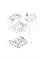
routine maintenance for one year for 500 units of printers and assuming that the printers are operated for 2 hours/day of 600 hours/year. The following codes are used to indicate the number of printers for which maintenance parts are ordered. 2 3 1 42114101 Rev.1 4 Figure B-1 Upper Cover Assy - Oki ML490 | Maintenance Manual - Page 118
Upper cover (N) Upper cover (W) Sheet guide assy (N) Sheet guide assy (W) Access cover assy (N) Access cover assy (W) Logo plate Logo plate Logo plate Logo plate Q'ty Q'ty Required Remarks 1 2 For ML490 1 2 For ML491 1 2 For ML490 1 2 For ML491 1 2 For ML490 1 2 For ML491 - Oki ML490 | Maintenance Manual - Page 119
1 6 8 9 7 2 10 3 11 4 5 Figure B-2 Printer General Assy 42114101 Rev.1 119 / - Oki ML490 | Maintenance Manual - Page 120
11 Table B-2 Printer General Assy Description Q'ty Q'ty Required Remarks Platen Knob 1 1 Power supply board (TPW) 1 9 Control board (TFS) 1 9 Operator panel board (LEOP) 1 3 Operation panel 1 2 AC cord for 120V AC cord for 230V AC cord for 230V 1 1 1 1 1 1 Print head (24 - Oki ML490 | Maintenance Manual - Page 121
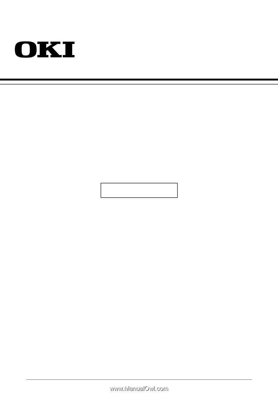
30 23 32 35 34 33 17 9 2 39 10 21 22 13 16 37 B A 41 1 31 29 36 A 28 38 24 40 39 7 6 15 14 5 42 4 3 11 20 18 19 12 27 8 B 25 26 Figure B-3 Printer Unit 42114101 Rev.1 121 / - Oki ML490 | Maintenance Manual - Page 122
20 50931601 21 41737902 22 53349401 53349501 23 50114801 50114901 24 40907901 40908001 25 50923502 Table B-3 Printer Unit (1/2) Description Main chassis assy (N) Main chassis assy (W) Bottom paper end lever Pressure spring (F) Roller holder (F) Front pressure roller Release shaft (N) Release shaft - Oki ML490 | Maintenance Manual - Page 123
Drive shaft Tractor sheet guide Head cable film (W) Change gear shaft FAN FAN cover Shield sheet (Front) Shield sheet (Front) FG spring F Support spring Q'ty Q'ty Required Remarks 1 1 For ML490 1 1 For ML491 1 1 1 1 For ML490 1 1 For ML491 1 1 1 2 For ML490 1 2 For ML491 - Oki ML490 | Maintenance Manual - Page 124
12 8 10 14 11 1 13 3 9 6 5 42114101 Rev.1 7-1 7-2 Figure B-4 Carriage Assy 124 / - Oki ML490 | Maintenance Manual - Page 125
2 Guide roller holder assy 1 2 Space motor assy (24) 1 Head cable (23) 1 Head cable (20) 1 PC connector (36/40) 1 Gear case assy 1 Head clamp holder 1 Head plate 1 Ribbon protector frame 1 Back up roller holder spring 1 Guide roller holder spring 1 4 5 ML490 ML491 5 ML490 - Oki ML490 | Maintenance Manual - Page 126
[Pull-Tractor] 2 1 3 [Bottom-Tractor] 4 [I/F Board] 5 6 7 42114101 Rev.1 Figure B-5 Option Spare Parts 126 / - Oki ML490 | Maintenance Manual - Page 127
Spare Parts Description Pull and bottom tractor assy (L) Pull and bottom tractor assy (R) Tractor cover assy (N) Tractor cover assy (W) Bottom push stand (L) Bottom push stand (R) Paper knife (N) Paper knife (W) RS232C I/F board (LXHI) Q'ty Q'ty Required 1 2 Remarks 1 2 1 3 For ML490 - Oki ML490 | Maintenance Manual - Page 128
controls the following: (a.) Serial interface protocol and data transfer through a serial port. (b.) Message buffer. (c.) Transmission of parallel data to the printer. (2) 75189 An RS-232C standard line receiver (3) 75188 An RS-232C standard line driver. (4) ROM (No Mount) A 64Kbit ROM that contains - Oki ML490 | Maintenance Manual - Page 129
reset the printer. When the reset is canceled, the 80C51 CPU performs initialization. Initialization consists of setting the 80C51 timer, and setting the serial mode. 2.2.2. RS-232C interface The DTR, SSD, TD and RTS signals output by the 80C51 are converted to RS-232C signals by line driver 75188 - Oki ML490 | Maintenance Manual - Page 130
Yes Buffer overflow? Yes No Error? No error Store the received character in buffer. Parity error Store 40 H in buffer. Is the printer in DESELECT Yes state or is the paper low? No Is remaining Yes buffer space ≤ 256? No Yes Is remaining buffer space > 256 during No Has 200 ms or - Oki ML490 | Maintenance Manual - Page 131
Yes Buffer overflow? Yes No Error? No error Store the received character in buffer. Parity error Store 40 H in buffer. Is the printer in DESELECT state or is the paper low? No Is remaining buffer space < 256? No Has 200 ms elapsed after sending DC3 is turned on or has 1 second elapsed - Oki ML490 | Maintenance Manual - Page 132
. If not, perform the printers self test and thoroughly test the printers functionality. If the trouble is reproducible proceed to the troubleshooting section. 3.2 Troubleshooting (1) The data is not received using a serial interface. (2) Using a serial interface, the print data is omitted or the - Oki ML490 | Maintenance Manual - Page 133
A Yes Are ALE, PSEN, RD, WR, signals as specified in Figure C-6? 180ns 542ns 5V ALE 0V PSEN RD/WR 271ns 5V 0V 542ns 5V 0V Figure C-6 No Replace the Q3. Yes Are (T1) SELECT and (INTO) BUSY signals low level? No Check Q3 on the Control Board. Yes Are +9V and -9V input to Q1? No Replace - Oki ML490 | Maintenance Manual - Page 134
2 In receiving by serial interface, printing data is omitted or printing operation is not performed. Are RxD and SSD of Q3 as specified in Figure C-7? No Replace the Q2. Yes Are, WR, and BUS signals of - Oki ML490 | Maintenance Manual - Page 135
After the settings outlined in Section 3.3.1.1 are completed and power is turned on, the serial interface checks the message buffer memory and interface driver/receiver circuit. It then prints characters. To start and stop this test, push the SEL switch on the front of the printer. Details of
-
 1
1 -
 2
2 -
 3
3 -
 4
4 -
 5
5 -
 6
6 -
 7
7 -
8
-
9
-
10
-
11
-
12
-
13
-
14
-
15
-
16
-
17
-
18
-
19
-
20
-
21
-
22
-
23
-
24
-
25
-
26
-
27
-
28
-
29
-
30
-
31
-
32
-
33
-
34
-
35
-
36
-
37
-
38
-
39
-
40
-
41
-
42
-
43
-
44
-
45
-
46
-
47
-
48
-
49
-
50
-
51
-
52
-
53
-
54
-
55
-
56
-
57
-
58
-
59
-
60
-
61
-
62
-
63
-
64
-
65
-
66
-
67
-
68
-
69
-
70
-
71
-
72
-
73
-
74
-
75
-
76
-
77
-
78
-
79
-
80
-
81
-
82
-
83
-
84
-
85
-
86
-
87
-
88
-
89
-
90
-
91
-
92
-
93
-
94
-
95
-
96
-
97
-
98
-
99
-
100
-
101
-
102
-
103
-
104
-
105
-
106
-
107
-
108
-
109
-
110
-
111
-
112
-
113
-
114
-
115
-
116
-
117
-
118
-
119
-
120
-
121
-
122
-
123
-
124
-
125
-
126
-
127
-
128
-
129
-
130
-
131
-
132
-
133
-
134
-
135
 |
 |
42114101
Rev.1
1 / 135
ML490/491 PRINTER
Maintenance Manual
ODA