Oki ML490 Maintenance Manual - Page 24
LF Motor Control
 |
View all Oki ML490 manuals
Add to My Manuals
Save this manual to your list of manuals |
Page 24 highlights
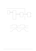
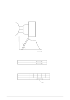
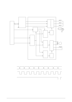
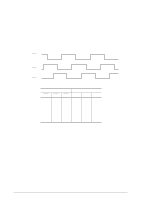
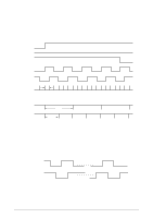
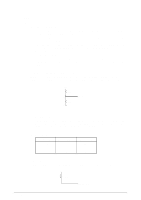
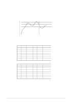
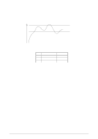
(2) Encoder Disk In the operation of the spacing motor, the PHASE-A and PHASE-B signals are generated when the encoder disk interrupts the photo sensor. The LSI divides these edge pulse signals in accordance with the print pitch, and sends the IPT signal to provide dot-on timing and carriage position detection timing. SPU SPV SPW PHASE-A PHASE-B 1/720" • UTILITY MODE IPT 10 CPI 12 CPI 15 CPI IPT 17 CPI 20 CPI 1/120" 1/240" (3) LF Motor Control The LF motor driver (MHM2025) drives the LF motor in two-phase or 1-2 phase bipolar, based on the phase changeover data and the output current data from the MPU. The data from the MPU is processed by a specific register contained in the LF motor driver to measure the overdrive time and to change the phase. PHASE-A PHASE-B [FORWARD] [REVERSE] 42114101 Rev.1 24 /
-
 1
1 -
2
-
3
-
4
-
5
-
6
-
7
-
8
-
9
-
10
-
11
-
12
-
13
-
14
-
15
-
16
-
17
-
18
-
 19
19 -
 20
20 -
 21
21 -
 22
22 -
 23
23 -
 24
24 -
 25
25 -
 26
26 -
 27
27 -
 28
28 -
 29
29 -
30
-
31
-
32
-
33
-
34
-
35
-
36
-
37
-
38
-
39
-
40
-
41
-
42
-
43
-
44
-
45
-
46
-
47
-
48
-
49
-
50
-
51
-
52
-
53
-
54
-
55
-
56
-
57
-
58
-
59
-
60
-
61
-
62
-
63
-
64
-
65
-
66
-
67
-
68
-
69
-
70
-
71
-
72
-
73
-
74
-
75
-
76
-
77
-
78
-
79
-
80
-
81
-
82
-
83
-
84
-
85
-
86
-
87
-
88
-
89
-
90
-
91
-
92
-
93
-
94
-
95
-
96
-
97
-
98
-
99
-
100
-
101
-
102
-
103
-
104
-
105
-
106
-
107
-
108
-
109
-
110
-
111
-
112
-
113
-
114
-
115
-
116
-
117
-
118
-
119
-
120
-
121
-
122
-
123
-
124
-
125
-
126
-
127
-
128
-
129
-
130
-
131
-
132
-
133
-
134
-
135
 |
 |
