Oki ML490 Maintenance Manual - Page 77
When the Tractor Assy L
 |
View all Oki ML490 manuals
Add to My Manuals
Save this manual to your list of manuals |
Page 77 highlights
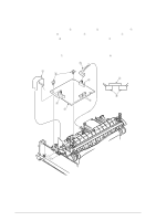
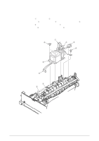
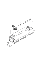
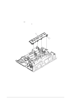
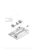
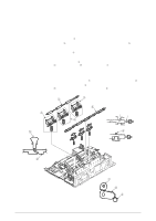
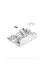
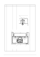
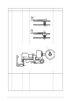
3.3.20 Rear Tractor Assy (1) Remove the printhead (see 3.3.1). (2) Remove the ribbon protector (see 3.3.2). (3) Remove the pull-up roller assy (see 3.3.3) (4) Remove the upper cover (see 3.3.4 (1) - (5)). (5) Remove the reset spring (see 3.3.17 (3)) (6) Remove the tractor gear 1. (7) Shift the drive shaft 2 to the right side to remove (in the direction of the arrow). (8) To perform mounting, follow the reverse procedure of removal. Remark on assembly: (1) When the Tractor Assy (L) 3 (R) 4 have been detached from the Drive Shaft, align the protrusions 5 of the Pin Tractor Wheels to the same direction before assembly. 5 4 2 3 1 42114101 Rev.1 77 /
-
 1
1 -
2
-
3
-
4
-
5
-
6
-
7
-
8
-
9
-
10
-
11
-
12
-
13
-
14
-
15
-
16
-
17
-
18
-
19
-
20
-
21
-
22
-
23
-
24
-
25
-
26
-
27
-
28
-
29
-
30
-
31
-
32
-
33
-
34
-
35
-
36
-
37
-
38
-
39
-
40
-
41
-
42
-
43
-
44
-
45
-
46
-
47
-
48
-
49
-
50
-
51
-
52
-
53
-
54
-
55
-
56
-
57
-
58
-
59
-
60
-
61
-
62
-
63
-
64
-
65
-
66
-
67
-
68
-
69
-
70
-
71
-
 72
72 -
 73
73 -
 74
74 -
 75
75 -
 76
76 -
 77
77 -
 78
78 -
 79
79 -
 80
80 -
 81
81 -
 82
82 -
83
-
84
-
85
-
86
-
87
-
88
-
89
-
90
-
91
-
92
-
93
-
94
-
95
-
96
-
97
-
98
-
99
-
100
-
101
-
102
-
103
-
104
-
105
-
106
-
107
-
108
-
109
-
110
-
111
-
112
-
113
-
114
-
115
-
116
-
117
-
118
-
119
-
120
-
121
-
122
-
123
-
124
-
125
-
126
-
127
-
128
-
129
-
130
-
131
-
132
-
133
-
134
-
135
 |
 |

42114101
Rev.1
77 /
3.3.20 Rear Tractor Assy
(1)
Remove the printhead (see 3.3.1).
(2)
Remove the ribbon protector (see 3.3.2).
(3)
Remove the pull-up roller assy (see 3.3.3)
(4)
Remove the upper cover (see 3.3.4 (1) – (5)).
(5)
Remove the reset spring (see 3.3.17 (3))
(6)
Remove the tractor gear
1
.
(7)
Shift the drive shaft
2
to the right side to remove (in the direction of the arrow).
(8)
To perform mounting, follow the reverse procedure of removal.
Remark on assembly:
(1)
When the Tractor Assy (L)
3
(R)
4
have been detached from the Drive Shaft, align
the protrusions
5
of the Pin Tractor Wheels to the same direction before assembly.
5
3
4
2
1