Oki ML490 Maintenance Manual - Page 54
Assembly/disassembly
 |
View all Oki ML490 manuals
Add to My Manuals
Save this manual to your list of manuals |
Page 54 highlights
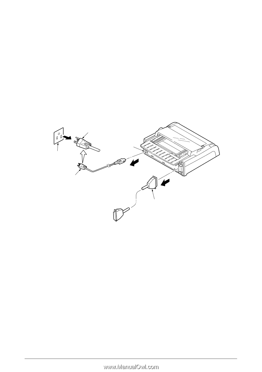
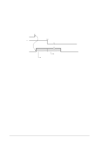
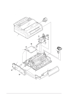
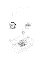
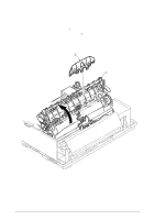
3. ASSEMBLY/DISASSEMBLY This section explains the procedures for removing and installing various assemblies and units in the field. Description is mainly limited to the removal procedure; installation should basically be performed in the reverse sequence of the removal procedure. 3.1 Precaution for Parts Replacement (1) Remove the AC cable and the interface cable before disassembling or assembling. (a) Turn off the AC power switch. Remove the AC input plug of the AC cable from the receptacle. Remove the AC cable from the inlet on the printer. (b) To connect the AC cable again, connect it to the inlet on the printer first, then insert the AC input plug into a receptacle. AC input plug Inlet AC receptacle AC cable Interface cable (2) Do not disassemble the printer as long as it is operating normally. (3) Do not remove unnecessary parts, and limit the disassembly area as much as possible. (4) Use the designated service tools. (5) Carry out disassembly in the prescribed sequence; otherwise, damage to the parts may result. (6) It is advisable to temporarily install screws, snap rings and other small parts in their original positions to avoid losing them. (7) Whenever handling the microprocessors, ROM, RAM IC chips and boards, do not use gloves which may cause static electricity. (8) Do not place the printed circuit board directly on the equipment or on the floor. (9) If adjustment is specified in the middle of installation, follow the instructions. 42114101 Rev.1 54 /
-
 1
1 -
2
-
3
-
4
-
5
-
6
-
7
-
8
-
9
-
10
-
11
-
12
-
13
-
14
-
15
-
16
-
17
-
18
-
19
-
20
-
21
-
22
-
23
-
24
-
25
-
26
-
27
-
28
-
29
-
30
-
31
-
32
-
33
-
34
-
35
-
36
-
37
-
38
-
39
-
40
-
41
-
42
-
43
-
44
-
45
-
46
-
47
-
48
-
 49
49 -
 50
50 -
 51
51 -
 52
52 -
 53
53 -
 54
54 -
 55
55 -
 56
56 -
 57
57 -
 58
58 -
 59
59 -
60
-
61
-
62
-
63
-
64
-
65
-
66
-
67
-
68
-
69
-
70
-
71
-
72
-
73
-
74
-
75
-
76
-
77
-
78
-
79
-
80
-
81
-
82
-
83
-
84
-
85
-
86
-
87
-
88
-
89
-
90
-
91
-
92
-
93
-
94
-
95
-
96
-
97
-
98
-
99
-
100
-
101
-
102
-
103
-
104
-
105
-
106
-
107
-
108
-
109
-
110
-
111
-
112
-
113
-
114
-
115
-
116
-
117
-
118
-
119
-
120
-
121
-
122
-
123
-
124
-
125
-
126
-
127
-
128
-
129
-
130
-
131
-
132
-
133
-
134
-
135
 |
 |