Oki ML490 Maintenance Manual - Page 84
Rear or Bottom
 |
View all Oki ML490 manuals
Add to My Manuals
Save this manual to your list of manuals |
Page 84 highlights
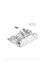
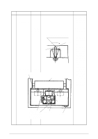
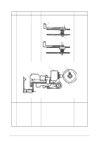
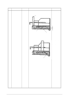
No. Item Specification 4-2 Gap between the platen and the paper pan 1±0.5 Rear Platen 1±0.5 (ReBaorpt,toosmition) 4-3 Gap between the platen and the pressure roller Rear Platen Front pressure roller Drawing Change lever Adjustment method Confirm followings. Bottom (1) When the change lever is set at Friction position, the gap between the platen and the paper pan at the rear side shall be 1±0.5mm. Paper pan (2) When the change lever is set at Rear or Bottom position, the gap between the platen and the paper pan at the front side shall be 1±0.5 mm. (A1t ±fr0ic.t5ion) Friction position Rear, Bottom position Change lever (Center friction) Bottom Paper pan Pressure roller Confirm followings. (1) When the change lever is set at Friction position, all the pressure rollers shall be pressed to the platen. (2) When the change lever is set at Rear or Bottom position, the gap between the platen and the pressure roller at the rear side shall be 3mm. The front pressure rollers shall be pressed to the platen. 42114101 Rev.1 84 /
-
 1
1 -
2
-
3
-
4
-
5
-
6
-
7
-
8
-
9
-
10
-
11
-
12
-
13
-
14
-
15
-
16
-
17
-
18
-
19
-
20
-
21
-
22
-
23
-
24
-
25
-
26
-
27
-
28
-
29
-
30
-
31
-
32
-
33
-
34
-
35
-
36
-
37
-
38
-
39
-
40
-
41
-
42
-
43
-
44
-
45
-
46
-
47
-
48
-
49
-
50
-
51
-
52
-
53
-
54
-
55
-
56
-
57
-
58
-
59
-
60
-
61
-
62
-
63
-
64
-
65
-
66
-
67
-
68
-
69
-
70
-
71
-
72
-
73
-
74
-
75
-
76
-
77
-
78
-
 79
79 -
 80
80 -
 81
81 -
 82
82 -
 83
83 -
 84
84 -
 85
85 -
 86
86 -
 87
87 -
 88
88 -
 89
89 -
90
-
91
-
92
-
93
-
94
-
95
-
96
-
97
-
98
-
99
-
100
-
101
-
102
-
103
-
104
-
105
-
106
-
107
-
108
-
109
-
110
-
111
-
112
-
113
-
114
-
115
-
116
-
117
-
118
-
119
-
120
-
121
-
122
-
123
-
124
-
125
-
126
-
127
-
128
-
129
-
130
-
131
-
132
-
133
-
134
-
135
 |
 |
