Oki ML490 Maintenance Manual - Page 26
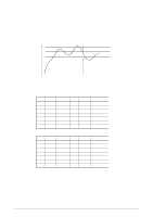
From the illustration above, you can see that the command and the command response are output at
 |
View all Oki ML490 manuals
Add to My Manuals
Save this manual to your list of manuals |
Page 26 highlights
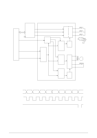
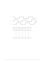
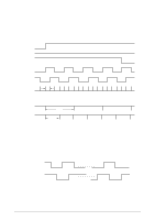
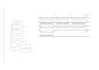
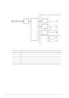
42114101 Rev.1 OPTXD 6 1 2 3 2 3 1 5 or 8 7 bit0 bit7 Command (first) Command (second) Power ON OPCLK Write instruction for IC reset 1 IC write for LED data, 2 etc. OPRXD OPCLR-N bit0 bit7 Command response (first) Note Command response (second) Read instruction for 3 data read Response check for OK or NG YES 5 6 4 NO Error notification Instruction for retransmission Reset within IC 7 8 Note: From the illustration above, you can see that the command and the command response are output at the same time. This is because the bit 0 to bit 3 of OPRXD are fixed so that the response can be returned before decoding the command. 26 /
-
 1
1 -
2
-
3
-
4
-
5
-
6
-
7
-
8
-
9
-
10
-
11
-
12
-
13
-
14
-
15
-
16
-
17
-
18
-
19
-
20
-
 21
21 -
 22
22 -
 23
23 -
 24
24 -
 25
25 -
 26
26 -
 27
27 -
 28
28 -
 29
29 -
 30
30 -
 31
31 -
32
-
33
-
34
-
35
-
36
-
37
-
38
-
39
-
40
-
41
-
42
-
43
-
44
-
45
-
46
-
47
-
48
-
49
-
50
-
51
-
52
-
53
-
54
-
55
-
56
-
57
-
58
-
59
-
60
-
61
-
62
-
63
-
64
-
65
-
66
-
67
-
68
-
69
-
70
-
71
-
72
-
73
-
74
-
75
-
76
-
77
-
78
-
79
-
80
-
81
-
82
-
83
-
84
-
85
-
86
-
87
-
88
-
89
-
90
-
91
-
92
-
93
-
94
-
95
-
96
-
97
-
98
-
99
-
100
-
101
-
102
-
103
-
104
-
105
-
106
-
107
-
108
-
109
-
110
-
111
-
112
-
113
-
114
-
115
-
116
-
117
-
118
-
119
-
120
-
121
-
122
-
123
-
124
-
125
-
126
-
127
-
128
-
129
-
130
-
131
-
132
-
133
-
134
-
135
 |
 |

42114101
Rev.1
26 /
Note:
From the illustration above, you can see that the command and the command response are output at the same time. This is because
the bit 0 to bit 3 of OPRXD are fixed so that the response can be returned before decoding the command.
OPTXD
OPCLK
OPRXD
OPCLR-N
1
2
3
2
31
6
7
5
or
8
bit0
bit7
Command (first)
Command (second)
Command response (first)
Command response (second)
Note
bit0
bit7
Reset
within IC
Power ON
Write instruction for IC reset
IC write for LED data,
etc.
Read instruction for
data read
Response check
for OK or NG
Error notification
Instruction for
retransmission
1
2
3
4
7
8
5
6
NO
YES