Oki ML490 Maintenance Manual - Page 69
Control Board TFS
 |
View all Oki ML490 manuals
Add to My Manuals
Save this manual to your list of manuals |
Page 69 highlights
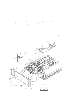
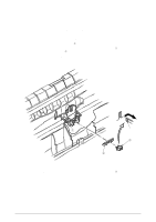
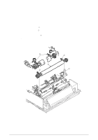
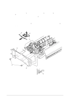
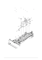
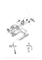
3.3.12 Control Board (TFS) (1) Remove the upper cover (see 3.3.4 (1) - (5)). (2) Remove two screws 1, and release the Control Board 2 and PCB sheet 5 by lifting clamp 4. (3) Disconnect all cables from Control Board 2. (4) To install, follow the removal steps in the reverse order. Note on installation: (1) Insert one sensor lever 3 between sensor when installing the Control Board 2. (2) Make sure that there is not any dust or oil on the connector contact section A. If it is found, wipe it off by alcohol. 2 4 4 2 A 3 1 5 Sensor 3 42114101 Rev.1 69 /
-
 1
1 -
2
-
3
-
4
-
5
-
6
-
7
-
8
-
9
-
10
-
11
-
12
-
13
-
14
-
15
-
16
-
17
-
18
-
19
-
20
-
21
-
22
-
23
-
24
-
25
-
26
-
27
-
28
-
29
-
30
-
31
-
32
-
33
-
34
-
35
-
36
-
37
-
38
-
39
-
40
-
41
-
42
-
43
-
44
-
45
-
46
-
47
-
48
-
49
-
50
-
51
-
52
-
53
-
54
-
55
-
56
-
57
-
58
-
59
-
60
-
61
-
62
-
63
-
 64
64 -
 65
65 -
 66
66 -
 67
67 -
 68
68 -
 69
69 -
 70
70 -
 71
71 -
 72
72 -
 73
73 -
 74
74 -
75
-
76
-
77
-
78
-
79
-
80
-
81
-
82
-
83
-
84
-
85
-
86
-
87
-
88
-
89
-
90
-
91
-
92
-
93
-
94
-
95
-
96
-
97
-
98
-
99
-
100
-
101
-
102
-
103
-
104
-
105
-
106
-
107
-
108
-
109
-
110
-
111
-
112
-
113
-
114
-
115
-
116
-
117
-
118
-
119
-
120
-
121
-
122
-
123
-
124
-
125
-
126
-
127
-
128
-
129
-
130
-
131
-
132
-
133
-
134
-
135
 |
 |

42114101
Rev.1
69 /
2
4
4
2
1
5
3
3
Sensor
A
3.3.12 Control Board (TFS)
(1)
Remove the upper cover (see 3.3.4 (1) – (5)).
(2)
Remove two screws
1
, and release the Control Board
2
and PCB sheet
5
by lifting clamp
4
.
(3)
Disconnect all cables from Control Board
2
.
(4)
To install, follow the removal steps in the reverse order.
Note on installation:
(1)
Insert one sensor lever
3
between sensor when installing the Control Board
2
.
(2)
Make sure that there is not any dust or oil on the connector contact section A. If it
is found, wipe it off by alcohol.