Oki ML490 Maintenance Manual - Page 34
Spacing operation See
 |
View all Oki ML490 manuals
Add to My Manuals
Save this manual to your list of manuals |
Page 34 highlights
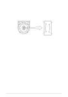
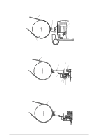
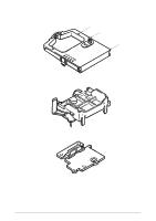
2.2.2 Spacing operation (See Figure 2-4.) The spacing mechanism consists of a carriage shaft mounted in parallel with the platen, and a carriage frame that moves along the shaft. It is driven by a DC motor mounted on the bottom of the carriage frame. Items included in the spacing mechanism are as follows: (a) DC motor with motor gear (b) Carriage frame (stationary yoke and motor driver board included) (c) Carriage shaft (d) Space rack (e) Sensor (f) Encoder disk (1) Spacing operation The carriage frame, on which the printhead and space motor are mounted, moves along the carriage shaft in parallel with the platen. When the spacing motor rotates counterclockwise, the driving force is transmitted to the motor gear. As the motor gear rotates, the carriage moves from left to right. Mechanically, it is designed in such a way that for every revolution of the DC motor, the carriage frame moves 0.8 inch (20.32 mm). At the same time the encoder disk rotates together with the motor and passes the sensor. The position of the carriage frame can be determined by counting the interrupts detected by the sensor. In the same way, the rotation of the space motor can be recognized and controlled by measuring the cycle of interrupts detected by the sensor. Print Head Carriage shaft Carriage frame Space rack Encoder disk Encoder sensor Motor gear Slider Guide rail Figure 2-4 42114101 Rev.1 34 /
-
 1
1 -
2
-
3
-
4
-
5
-
6
-
7
-
8
-
9
-
10
-
11
-
12
-
13
-
14
-
15
-
16
-
17
-
18
-
19
-
20
-
21
-
22
-
23
-
24
-
25
-
26
-
27
-
28
-
 29
29 -
 30
30 -
 31
31 -
 32
32 -
 33
33 -
 34
34 -
 35
35 -
 36
36 -
 37
37 -
 38
38 -
 39
39 -
40
-
41
-
42
-
43
-
44
-
45
-
46
-
47
-
48
-
49
-
50
-
51
-
52
-
53
-
54
-
55
-
56
-
57
-
58
-
59
-
60
-
61
-
62
-
63
-
64
-
65
-
66
-
67
-
68
-
69
-
70
-
71
-
72
-
73
-
74
-
75
-
76
-
77
-
78
-
79
-
80
-
81
-
82
-
83
-
84
-
85
-
86
-
87
-
88
-
89
-
90
-
91
-
92
-
93
-
94
-
95
-
96
-
97
-
98
-
99
-
100
-
101
-
102
-
103
-
104
-
105
-
106
-
107
-
108
-
109
-
110
-
111
-
112
-
113
-
114
-
115
-
116
-
117
-
118
-
119
-
120
-
121
-
122
-
123
-
124
-
125
-
126
-
127
-
128
-
129
-
130
-
131
-
132
-
133
-
134
-
135
 |
 |
