Oki ML490 Maintenance Manual - Page 25
Operation Panel
 |
View all Oki ML490 manuals
Add to My Manuals
Save this manual to your list of manuals |
Page 25 highlights
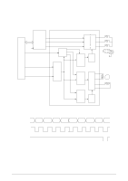
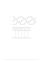
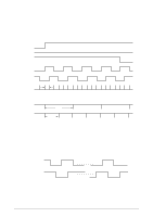
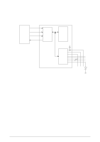
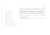
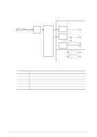
2.1.7 Operation Panel The clock synchronization OPCLK of LSI is used to input the switch data and output the LED data through the operation panel control IC. LSI OPTD OPCK NPA2 OPRD OPTXD 48 OPCLK 47 OPCLR-N 45 OPRXD 46 Operation panel control IC Command and Data latch LED driver +5V Switch controller A 2-byte (15 bits + 1 even parity bit) command (OPTXD) is transmitted to the Operation panel contol IC in synchronization with the OPCLK signal. The Operation panel control IC decodes this command and when it is found to be legal, returns a 2-byte command response back to the LSI which includes data on Switch information, LED status, receive command ACK/NAK and 1 odd parity bit. Any transmission errors found cause the command to be reissued after the transmission of the OPCLR-N signal. 42114101 Rev.1 25 /
-
 1
1 -
2
-
3
-
4
-
5
-
6
-
7
-
8
-
9
-
10
-
11
-
12
-
13
-
14
-
15
-
16
-
17
-
18
-
19
-
 20
20 -
 21
21 -
 22
22 -
 23
23 -
 24
24 -
 25
25 -
 26
26 -
 27
27 -
 28
28 -
 29
29 -
 30
30 -
31
-
32
-
33
-
34
-
35
-
36
-
37
-
38
-
39
-
40
-
41
-
42
-
43
-
44
-
45
-
46
-
47
-
48
-
49
-
50
-
51
-
52
-
53
-
54
-
55
-
56
-
57
-
58
-
59
-
60
-
61
-
62
-
63
-
64
-
65
-
66
-
67
-
68
-
69
-
70
-
71
-
72
-
73
-
74
-
75
-
76
-
77
-
78
-
79
-
80
-
81
-
82
-
83
-
84
-
85
-
86
-
87
-
88
-
89
-
90
-
91
-
92
-
93
-
94
-
95
-
96
-
97
-
98
-
99
-
100
-
101
-
102
-
103
-
104
-
105
-
106
-
107
-
108
-
109
-
110
-
111
-
112
-
113
-
114
-
115
-
116
-
117
-
118
-
119
-
120
-
121
-
122
-
123
-
124
-
125
-
126
-
127
-
128
-
129
-
130
-
131
-
132
-
133
-
134
-
135
 |
 |
