Oki ML490 Maintenance Manual - Page 78
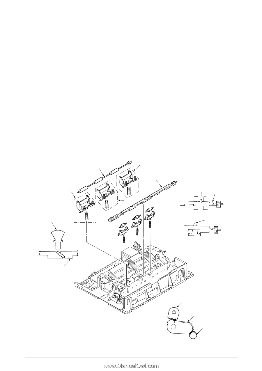
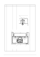
Match the Main Frame Rib A with the protrusion B of the Release Shaft.
 |
View all Oki ML490 manuals
Add to My Manuals
Save this manual to your list of manuals |
Page 78 highlights
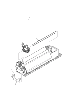
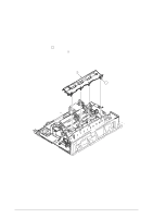
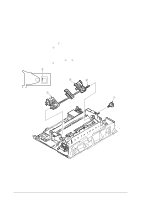
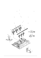
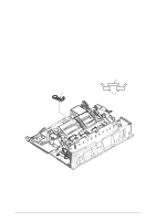
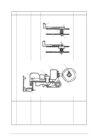
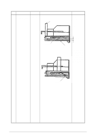
3.3.21 Rear Pressure Assy (1) Remove the upper cover (see 3.3.4 (1) - (5)). (2) Remove the change lever and gears (see 3.3.17). (3) Remove the paper pan (see 3.3.19). (4) Remove the rear pressure roller 1. (5) Rotate the release shaft 2 and move it to the left to detach the release shaft 2. Match the Main Frame Rib A with the protrusion B of the Release Shaft. (6) Remove rear pressure SP assy 3. (7) To install, follow the removal step in the reverse order. Note: (1) At mounting release shaft 2, pay attention to the gear engagement of release shaft 2, change arm lever 6, change gear shaft 7. (2) There are 5 Rear pressure Spring Assemblies. Use two pieces which have larger spring diameter on the right side. Use three remaining pieces on the left side (for ML491). (3) Make sure that the Release Shaft 2 will be on top of the Support spring 4. (4) To assemble the Release Shaft 2, make sure that the protrusion of the switch lever 5 is in the U groove of the Release Shaft 2. 3 1 2 3 3 A B 5 4 2 42114101 Rev.1 7 6 2 78 /
-
 1
1 -
2
-
3
-
4
-
5
-
6
-
7
-
8
-
9
-
10
-
11
-
12
-
13
-
14
-
15
-
16
-
17
-
18
-
19
-
20
-
21
-
22
-
23
-
24
-
25
-
26
-
27
-
28
-
29
-
30
-
31
-
32
-
33
-
34
-
35
-
36
-
37
-
38
-
39
-
40
-
41
-
42
-
43
-
44
-
45
-
46
-
47
-
48
-
49
-
50
-
51
-
52
-
53
-
54
-
55
-
56
-
57
-
58
-
59
-
60
-
61
-
62
-
63
-
64
-
65
-
66
-
67
-
68
-
69
-
70
-
71
-
72
-
 73
73 -
 74
74 -
 75
75 -
 76
76 -
 77
77 -
 78
78 -
 79
79 -
 80
80 -
 81
81 -
 82
82 -
 83
83 -
84
-
85
-
86
-
87
-
88
-
89
-
90
-
91
-
92
-
93
-
94
-
95
-
96
-
97
-
98
-
99
-
100
-
101
-
102
-
103
-
104
-
105
-
106
-
107
-
108
-
109
-
110
-
111
-
112
-
113
-
114
-
115
-
116
-
117
-
118
-
119
-
120
-
121
-
122
-
123
-
124
-
125
-
126
-
127
-
128
-
129
-
130
-
131
-
132
-
133
-
134
-
135
 |
 |