Oki ML490 Maintenance Manual - Page 58
Oki ML490 Manual
 |
View all Oki ML490 manuals
Add to My Manuals
Save this manual to your list of manuals |
Page 58 highlights
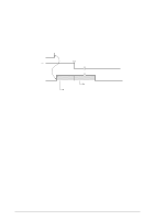
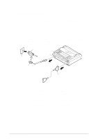
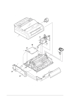
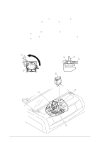
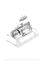
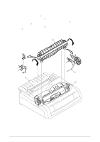
3.3.1 Printhead (1) Open the access over. (2) Pull up and rotate the head clamp 1 to unclamp the printhead 2 as shown Figure 3-2. (3) Disconnect the printhead 2 from PC connector 3. (4) To install, follow the removal steps in the reverse order. Notes on installation: (1) Insert the printhead 2 into the PC connector 3 while pushing it against the carriage frame 4. (2) The head clamp 1 must surely be sandwiched between printhead 2 and carriage frame 4 as shown Figure 3-3. (3) Be sure to check the gap between platen and printhead (see 4). (4) Be careful not to touch the print head while it is very hot. (5) Make sure that there is not any dust or oil on the connector contact section A. If it is found, wipe it off by alcohol. 1 4 2 1 2 Figure 3-2 2 Figure 3-3 A 4 1 42114101 Rev.1 3 58 /
-
 1
1 -
2
-
3
-
4
-
5
-
6
-
7
-
8
-
9
-
10
-
11
-
12
-
13
-
14
-
15
-
16
-
17
-
18
-
19
-
20
-
21
-
22
-
23
-
24
-
25
-
26
-
27
-
28
-
29
-
30
-
31
-
32
-
33
-
34
-
35
-
36
-
37
-
38
-
39
-
40
-
41
-
42
-
43
-
44
-
45
-
46
-
47
-
48
-
49
-
50
-
51
-
52
-
 53
53 -
 54
54 -
 55
55 -
 56
56 -
 57
57 -
 58
58 -
 59
59 -
 60
60 -
 61
61 -
 62
62 -
 63
63 -
64
-
65
-
66
-
67
-
68
-
69
-
70
-
71
-
72
-
73
-
74
-
75
-
76
-
77
-
78
-
79
-
80
-
81
-
82
-
83
-
84
-
85
-
86
-
87
-
88
-
89
-
90
-
91
-
92
-
93
-
94
-
95
-
96
-
97
-
98
-
99
-
100
-
101
-
102
-
103
-
104
-
105
-
106
-
107
-
108
-
109
-
110
-
111
-
112
-
113
-
114
-
115
-
116
-
117
-
118
-
119
-
120
-
121
-
122
-
123
-
124
-
125
-
126
-
127
-
128
-
129
-
130
-
131
-
132
-
133
-
134
-
135
 |
 |
