Oki ML490 Maintenance Manual - Page 27
V to 37V
 |
View all Oki ML490 manuals
Add to My Manuals
Save this manual to your list of manuals |
Page 27 highlights
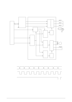
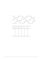
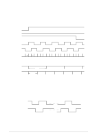
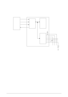
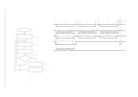
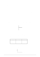
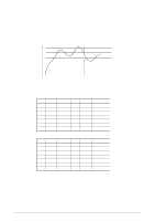
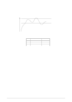
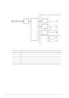
2.1.8 Alarm Circuit (1) AC Fuse open alarm (a) Head drive time alarm circuit This circuit monitors the drive time using the HDALM signal interlocked with the overdrive signal of each drive circuit. If the drive time of any drive circuit exceeds the specified time, the drive fault alarm circuit sends an ALM-N signal to turn on the Thyristor. This cause the secondary coil (50V) of the transformer to be short-circuited, causing an overcurrent to flow through the primary coil and making the AC fuse (transformer assy) open. (b) Overvoltage detection 50V, 12V and 5V voltages are monitored, at overvoltage alarm circuit turn-on, the ALM-N signal is transmitted to the thyristor, then the AC fuse (transformer assy) opens. (2) Alarm processing when DC power is low. 50V is converted into the POWLEV signal (0V to +5V) by R753 and R524 and input into the A/D port of the MPU to control the drive time and the print speed (pass number) of the head. +50V R753 POWLEV R524 (a) Head drive time The head drive time is lengthened to compensate for the amount of voltage drop by monitoring the POWLEV signal once every 500 µ sec. to control and maintain the impact necessary for each printing pin at the fixed value. (b) Print speed Voltage, +50V 38V or more 25V to 37V 25V or less Pass number 1 Pass 1 Pass 1 Pass Print speed 100% 100~30% 30% (3) FAN alarm The MPU detects 5V on the FANALM signal even through the fan is driven. 5V R515 FANALM-P 42114101 Rev.1 27 /
-
 1
1 -
2
-
3
-
4
-
5
-
6
-
7
-
8
-
9
-
10
-
11
-
12
-
13
-
14
-
15
-
16
-
17
-
18
-
19
-
20
-
21
-
 22
22 -
 23
23 -
 24
24 -
 25
25 -
 26
26 -
 27
27 -
 28
28 -
 29
29 -
 30
30 -
 31
31 -
 32
32 -
33
-
34
-
35
-
36
-
37
-
38
-
39
-
40
-
41
-
42
-
43
-
44
-
45
-
46
-
47
-
48
-
49
-
50
-
51
-
52
-
53
-
54
-
55
-
56
-
57
-
58
-
59
-
60
-
61
-
62
-
63
-
64
-
65
-
66
-
67
-
68
-
69
-
70
-
71
-
72
-
73
-
74
-
75
-
76
-
77
-
78
-
79
-
80
-
81
-
82
-
83
-
84
-
85
-
86
-
87
-
88
-
89
-
90
-
91
-
92
-
93
-
94
-
95
-
96
-
97
-
98
-
99
-
100
-
101
-
102
-
103
-
104
-
105
-
106
-
107
-
108
-
109
-
110
-
111
-
112
-
113
-
114
-
115
-
116
-
117
-
118
-
119
-
120
-
121
-
122
-
123
-
124
-
125
-
126
-
127
-
128
-
129
-
130
-
131
-
132
-
133
-
134
-
135
 |
 |
