42114101
Rev.1
4 /
Contents
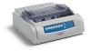
1. CONFIGURATION
...............................................................................................
6
1.1
Standard Printer Configuration
............................................................................................
6
1.2
Options
.................................................................................................................................
7
2.
THEORY OF OPERATION
..................................................................................
9
2.1
Electrical Operation
..............................................................................................................
9
2.1.1
Summary
.................................................................................................................
9
2.1.2
Microprocessor and the peripheral circuit
...............................................................
9
2.1.3
Initialization
...........................................................................................................
16
2.1.4
Interface Control
...................................................................................................
17
2.1.5
Print Control
..........................................................................................................
20
2.1.6
SP/LF Motor Control
.............................................................................................
22
2.1.7
Operation Panel
....................................................................................................
25
2.1.8
Alarm Circuit
.........................................................................................................
27
2.1.9
Power Supply Circuit
.............................................................................................
30
2.2
Mechanical Operation
........................................................................................................
31
2.2.1
Printhead mechanism and operation (See Figure 2-2.)
........................................
31
2.2.2
Spacing operation (See Figure 2-4.)
.....................................................................
34
2.2.3
Head gap adjusting (See Figure 2-5.)
...................................................................
35
2.2.4
Ribbon drive (See Figure 2-6.)
..............................................................................
37
2.2.5
Paper feed operation
............................................................................................
39
2.2.6
Paper detection mechanism (See Figure 2-14.)
...................................................
49
2.2.7
Automatic sheet feed
............................................................................................
51
2.2.8
Paper park function (continuous paper)
................................................................
53
3. ASSEMBLY/DISASSEMBLY
..............................................................................
54
3.1
Precaution for Parts Replacement
.....................................................................................
54
3.2
Service Tools
.....................................................................................................................
55
3.3
Disassembly/Reassembly Procedure
................................................................................
56
3.3.1
Printhead
...............................................................................................................
58
3.3.2
Ribbon Protector
...................................................................................................
59
3.3.3
Pull-up Roller Assy
................................................................................................
60
3.3.4
Upper Cover Assy, Access Cover Assy and Sheet Guide Assy
...........................
61
3.3.5
Gear Case Assy
....................................................................................................
62
3.3.6
PC Connector
.......................................................................................................
63
3.3.7
Space Motor, Guide Roller Assy
...........................................................................
64
3.3.8
Space Rack
...........................................................................................................
65
3.3.9
Carriage Cable
......................................................................................................
66
3.3.10
Backup Roller Holder Assy
...................................................................................
67
3.3.11
Platen Assy
...........................................................................................................
68
3.3.12
Control Board (TFS)
..............................................................................................
69
3.3.13
LF Motor
................................................................................................................
70
3.3.14
Operation Panel Board (LEOP)
............................................................................
71
3.3.15
Power Supply Board (TPW)
..................................................................................
72
3.3.16
Transformer Assy
..................................................................................................
73
3.3.17
Change Lever and Gears
......................................................................................
74
3.3.18
Carriage Shaft
.......................................................................................................
75
3.3.19
Paper Pan
.............................................................................................................
76
 1
1 2
2 3
3 4
4 5
5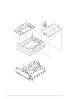 6
6 7
7 8
8 9
9 10
10

