Oki ML490 Maintenance Manual - Page 35
of the carriage cover will connect with the contact of the space motor PC board. The printer
 |
View all Oki ML490 manuals
Add to My Manuals
Save this manual to your list of manuals |
Page 35 highlights
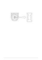
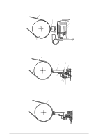
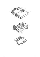
2.2.3 Head gap adjusting (See Figure 2-5.) The head gap adjusting lever moves back and forth to tilt the carriage frame, altering the gap between the printhead and the platen. The adjusting screw, which is connected to the adjusting gear rotates when the adjusting lever is moved creating a fine gap adjustment. If the adjusting gear is pushed down, the adjusting screw can be turned with a screw driver to change the coarse gap adjustment. When the adjusting lever is set to range ➁ ~ ➄ the contact which is attached to the under side of the carriage cover will connect with the contact of the space motor PC board. The printer will reduce the printing speed automatically to ensure that adequate printing pressure is maintained for multipart paper. And, the adjusting cam adjusts the headgap toward left and right side in accordance with the guide rail up and down as a position of the left end of it. 42114101 Rev.1 35 /
-
 1
1 -
2
-
3
-
4
-
5
-
6
-
7
-
8
-
9
-
10
-
11
-
12
-
13
-
14
-
15
-
16
-
17
-
18
-
19
-
20
-
21
-
22
-
23
-
24
-
25
-
26
-
27
-
28
-
29
-
 30
30 -
 31
31 -
 32
32 -
 33
33 -
 34
34 -
 35
35 -
 36
36 -
 37
37 -
 38
38 -
 39
39 -
 40
40 -
41
-
42
-
43
-
44
-
45
-
46
-
47
-
48
-
49
-
50
-
51
-
52
-
53
-
54
-
55
-
56
-
57
-
58
-
59
-
60
-
61
-
62
-
63
-
64
-
65
-
66
-
67
-
68
-
69
-
70
-
71
-
72
-
73
-
74
-
75
-
76
-
77
-
78
-
79
-
80
-
81
-
82
-
83
-
84
-
85
-
86
-
87
-
88
-
89
-
90
-
91
-
92
-
93
-
94
-
95
-
96
-
97
-
98
-
99
-
100
-
101
-
102
-
103
-
104
-
105
-
106
-
107
-
108
-
109
-
110
-
111
-
112
-
113
-
114
-
115
-
116
-
117
-
118
-
119
-
120
-
121
-
122
-
123
-
124
-
125
-
126
-
127
-
128
-
129
-
130
-
131
-
132
-
133
-
134
-
135
 |
 |
