Polaroid LDTV152 Owners Guide - Page 23
DVI Video Device Cable Box, Satellite, Receiver, DVD Player, or Other Device, Standard, Cable Box,
 |
UPC - 082400028051
View all Polaroid LDTV152 manuals
Add to My Manuals
Save this manual to your list of manuals |
Page 23 highlights
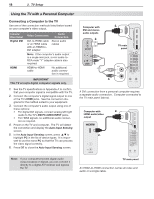
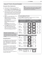
3. TV Connections 23 (480i / 480p / 720p / 1080i) (480i / 480p / 720p / 1080i) DVI Video Device (Cable Box, Satellite Receiver, DVD Player, or Other Device) Connect DVI devices (digital only) to the TV's HDMI input jacks. Analog stereo audio cables and a DVI-to-HDMI cable or DVI/HDMI adapter and HDMI cable are required. 1. Connect the DVI-to-HDMI cable (recommended) or HDMI cable with DVI/HDMI adapter from the DVI device's back panel to the TV's HDMI jack. Note: If you are using a DVI/HDMI adapter, it is important to connect the adapter to the DVI device for best performance. 2. Connect a set of audio cables from AUDIO OUT on the DVI device back panel to the DVI/PC INPUT AUDIO on the TV main panel. Connect the red cable to the R jack and the white cable to the L jack. Note: The HDMI connection supports copy protection (HDCP). Some devices require connection to an analog input first in order to view on-screen menus and to select DVI as the ouput. Please review your equipment instructions for DVI connectivity and compatibility. HDMI 4 3 2 TV main panel 1 IR- NetCommand Output / External Controller Input S-VIDEO INPUT3 Pr VIDEO L Pb AUDIO R DVI/PC L Y Y / VIDEO L AUDIO AUDIO R R INPUT2 L R AVR AUDIO OUTPUT INPUT1 DIGITAL AUDIO OUTPUT ANT2/AUX ANT1/MAIN DVI/PC L AUDIO R Digital DVI device DVI OUT AUDIO R L 1. 2. 1. 2. Standard Cable Box, Satellite Receiver, or Other Device with S-Video Required: S-Video cable and left/right analog stereo audio cables. 1. Connect the cable from the outside cable or satel- lite service to CABLE IN or SATELLITE IN on the cable box or satellite receiver. 2. Connect an S-Video cable from S-VIDEO OUT on the cable box or satellite receiver back panel to INPUT 3 S-VIDEO on the TV main panel. 3. Connect left (white) and right (red) audio cables from AUDIO OUT on the cable box or satellite receiver to INPUT 3 AUDIO L and R on the TV main panel. Note: Refer to the cable box or satellite receiver Owner's Guide for cable or dish antenna connections to the receiver. HDMI 4 TV main panel 2. S-VIDEO IR- NetCommand Output / External Controller Input S-VIDEO INPUT3 Pr VIDEO L Pb AUDIO R L DVI/PC Y Y / VIDEO L AUDL IO AUDIO AUDIO R R R INPUT2 L R AVR AUDIO OUTPUT INPUT1 DIGITAL AUDIO OUTPUT Connect audio cables to INPUT 3 AUDIO 3. Incoming cable from ANT2/AUX ANT1/MAIN wall Any S-Video device 2. S-VIDEO OUT 3. L R AUDIO 1. CABLE IN or SATELLITE IN Figure 4. Connecting a device with S-Video Figure 3. Connecting a digital DVI device
-
 1
1 -
2
-
3
-
4
-
5
-
6
-
7
-
8
-
9
-
10
-
11
-
12
-
13
-
14
-
15
-
16
-
17
-
 18
18 -
 19
19 -
 20
20 -
 21
21 -
 22
22 -
 23
23 -
 24
24 -
 25
25 -
 26
26 -
 27
27 -
 28
28 -
29
-
30
-
31
-
32
-
33
-
34
-
35
-
36
-
37
-
38
-
39
-
40
-
41
-
42
-
43
-
44
-
45
-
46
-
47
-
48
-
49
-
50
-
51
-
52
-
53
-
54
-
55
-
56
-
57
-
58
-
59
-
60
-
61
-
62
-
63
-
64
-
65
-
66
-
67
-
68
-
69
-
70
-
71
-
72
-
73
-
74
-
75
-
76
-
77
-
78
-
79
-
80
-
81
-
82
-
83
-
84
-
85
-
86
-
87
-
88
-
89
-
90
-
91
-
92
-
93
-
94
-
95
-
96
 |
 |
