Yamaha CL3 Cl Editor Owner's Manual - Page 18
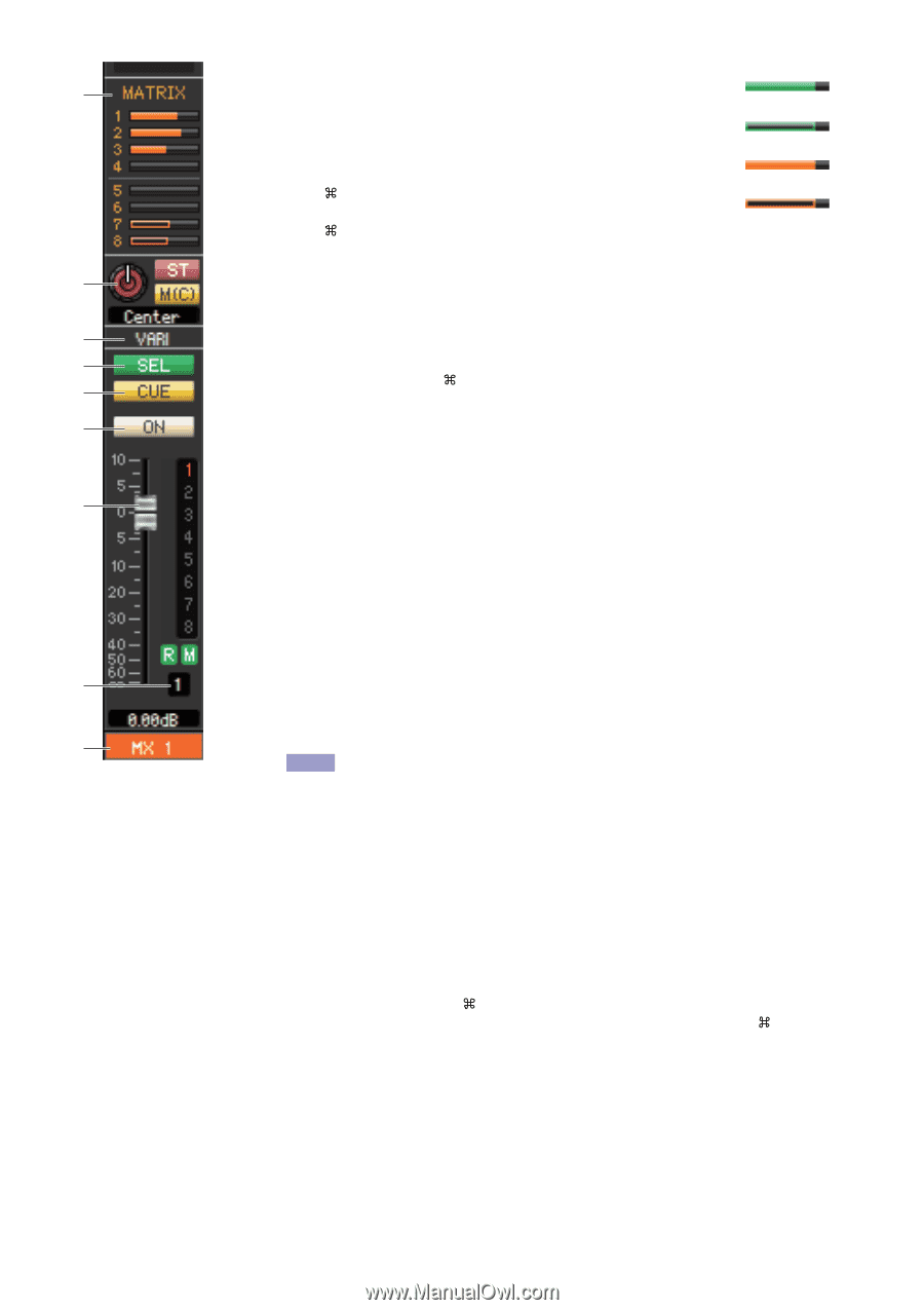
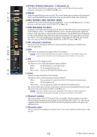
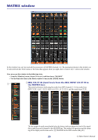
MATRIX MATRIX SEND, PAN/BALANCE/ST/MC, VARI/FIXED, SEL Channel selection, Fader
 |
View all Yamaha CL3 manuals
Add to My Manuals
Save this manual to your list of manuals |
Page 18 highlights
5 MATRIX (MATRIX SEND) These bar graphs indicate the send levels of the signals sent from the • Pre/on (green) 5 MIX channel to MATRIX 1-8 bus. You can also adjust the send levels by dragging a bar graph to left or right. While you drag the bar graph, • Pre/off (green) the send level is shown in the numerical display area for TO STEREO/ MONO. • Post/on (orange) You can set the minimum value (-∞ dB) by holding down the (< >) key of your computer keyboard and clicking the bar graph, or set the nominal value (0.00 dB) by holding down the (< >) key and key and clicking the bar graph. • Post/off (orange) The bar graph display will change as follows according to the send position (pre/post) and 6 on/off status of the signal sent from the MIX channel to the MATRIX buses. To switch a send on/off, click the channel number located at the left of the bar graph. 6 PAN/BALANCE/ST/M(C) 7 The PAN knob adjusts the panning of the signal that is sent from the mix channel to the 8 STEREO bus L/R channels (or the L/C/R channels.) You can set this to the center value by 9 holding down the (< >) key of your computer keyboard and clicking this knob. If assigned as a stereo bus, this adjusts the balance of the odd-numbered channel and even- 0 numbered channel. The stereo bus setting can be made in Mix Bus Setup of the Mixer Setup dialogbox. The [ST] button is an on/off switch for the signal that is sent from the mix channel to the STEREO bus. A The [M(C)] button is an on/off switch for the signal that is sent from the mix channel to the MONO bus. If LCR MODE is selected in the Selected Channel window, the [LCR] button will appear instead of the [ST] button and [MONO] button, and the [LCR] button will be an on/off switch for the signal that is sent from the mix channel to the LCR bus. 7 VARI/FIXED Indicates the type (VARI or FIXED) of the currently selected MIX bus. This parameter can be switched in Mix Bus Setup of the Mixer Setup dialogbox. B 8 SEL (Channel selection) Selects the MIX channel for which you want to make settings. 9 CUE C This button cue-monitors the signal of the MIX channel. NOTE If the Channel Select/Sends On Fader checkbox in the System Setup dia- log box is not checked, the [CUE] button will be hidden in the screen. 0 ON Switches the MIX channel on/off. The button is color-coded and indicates status as follows: White: MIX channel is on (normal mode.) Black: MIX channel/Send is off. Other colors: Send is on (SENDS ON FADER mode.) A Fader Adjusts the output level of the MIX channel. The current fader value is shown in the numeric box immediately below the fader. You can set this to the minimum value (-∞ dB) by holding down the (< >) key of your computer keyboard and clicking the fader knob, or set it to the nominal value (0.00 dB) by holding down the (< >) key and key and clicking the fader knob. 18 CL Editor Owner's Manual
-
 1
1 -
2
-
3
-
4
-
5
-
6
-
7
-
8
-
9
-
10
-
11
-
12
-
 13
13 -
 14
14 -
 15
15 -
 16
16 -
 17
17 -
 18
18 -
 19
19 -
 20
20 -
 21
21 -
 22
22 -
 23
23 -
24
-
25
-
26
-
27
-
28
-
29
-
30
-
31
-
32
-
33
-
34
-
35
-
36
-
37
-
38
-
39
-
40
-
41
-
42
-
43
-
44
-
45
-
46
-
47
-
48
-
49
-
50
-
51
-
52
-
53
-
54
-
55
-
56
-
57
-
58
-
59
-
60
-
61
-
62
-
63
-
64
-
65
-
66
-
67
-
68
-
69
-
70
-
71
-
72
-
73
-
74
-
75
-
76
-
77
-
78
-
79
-
80
-
81
-
82
-
83
-
84
-
85
-
86
-
87
-
88
-
89
 |
 |