Yamaha CL3 Cl Editor Owner's Manual - Page 31
KEY IN SOURCE, KEY IN FILTER, LIBRARY, Response curve, GR meter Gain Reduction meter - compression on
 |
View all Yamaha CL3 manuals
Add to My Manuals
Save this manual to your list of manuals |
Page 31 highlights
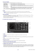
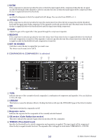
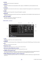
A KEY IN SOURCE Click this to select one of the following signals to use as the key-in source. SELF PRE EQ SELF POST EQ MIX OUT 21-24 CH 1-72 POST EQ STIN1L-STIN8R POST EQ The pre-EQ signal of the currently selected input channel The post-EQ signal of the currently selected input channel The output signal of the corresponding MIX channel immediately before the output attenuation The post-EQ signal of the corresponding input channel (however, you can only choose channels belonging to the same group, within the eleven groups CH1-8, CH9-16, CH17-24, CH25-32, CH33-40, CH41-48, CH49-56, CH57-64, CH65-72, and STIN1L-STIN4R, STIN5L-STIN8R) B CUE This button cue-monitors the currently selected key-in signal. This is not shown in the Additional View. NOTE If the Channel Select/Sends On Fader checkbox in the System Setup dialog box is not checked, the [CUE] button will be hidden in the screen. C KEY IN FILTER Select the type of filter applied to the selected key-in signal; HPF (high pass filter), BPF (band pass filter), or LPF (low pass filter.) The ON/OFF button switches the filter on/off. If you've selected BPF, use the two knobs to adjust the band pass frequency and Q. If you've selected HPF or LPF, use the knob to adjust the cutoff frequency. If COMPRESSOR/EXPANDER is selected 51 4 2 3 6 7 8 9 0 A B 1 TYPE Indicates the currently selected compressor or expander. You can click here to select the type. 2 LIBRARY This button accesses the dynamics library. Clicking this button will open the DYNAMICS page of the Library window. 3 ON This button switches on/off for the compressor or the expander. 4 Response curve Indicates the response for the compressor/expander of the currently selected channel. 5 GR meter (Gain Reduction meter) This meter indicates the amount of gain reduction produced by the compressor/expander. 6 THRESH (Threshold level) Specifies the threshold level at which the compressor/expander will operate. If the compressor is selected, the input signal will start being compressed when the key-in signal exceeds this level; compression will be removed when the signal falls below this level. If the expander is selected, the input signal will start being compressed when the key-in signal falls below this level; compression will be removed when the signal exceeds this level. 31 CL Editor Owner's Manual
-
 1
1 -
2
-
3
-
4
-
5
-
6
-
7
-
8
-
9
-
10
-
11
-
12
-
13
-
14
-
15
-
16
-
17
-
18
-
19
-
20
-
21
-
22
-
23
-
24
-
25
-
 26
26 -
 27
27 -
 28
28 -
 29
29 -
 30
30 -
 31
31 -
 32
32 -
 33
33 -
 34
34 -
 35
35 -
 36
36 -
37
-
38
-
39
-
40
-
41
-
42
-
43
-
44
-
45
-
46
-
47
-
48
-
49
-
50
-
51
-
52
-
53
-
54
-
55
-
56
-
57
-
58
-
59
-
60
-
61
-
62
-
63
-
64
-
65
-
66
-
67
-
68
-
69
-
70
-
71
-
72
-
73
-
74
-
75
-
76
-
77
-
78
-
79
-
80
-
81
-
82
-
83
-
84
-
85
-
86
-
87
-
88
-
89
 |
 |