Yamaha CL3 Cl Editor Owner's Manual - Page 64
Ch 1-72, Stin1l-stin8r, Ins Ch 1-72, Ins Mix 1-24, Ins Mtrx1-8, Ins St L, Ins St R, Ins Mc
 |
View all Yamaha CL3 manuals
Add to My Manuals
Save this manual to your list of manuals |
Page 64 highlights
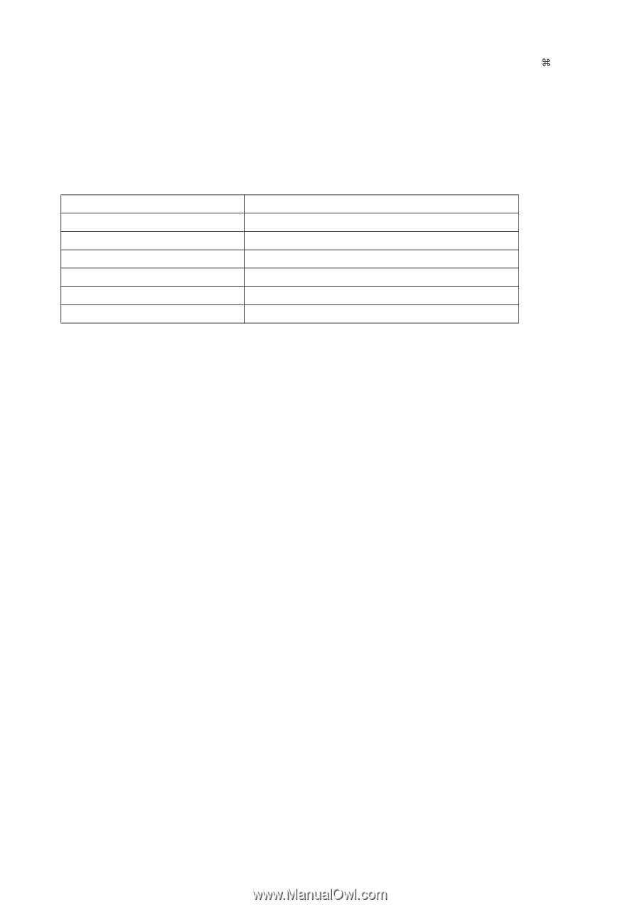
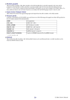
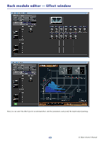
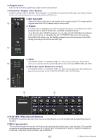
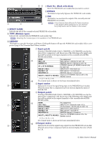
3 Module graphic This area shows a graphic of the PREMIUM rack module that is currently assigned to the rack, and the parameters of that module. Double-click this to open the module editor for that rack unit. By holding down the (< >) key of your computer keyboard and double-clicking this, you can open multiple rack module editors. For these additional editors, the rack select buttons are not linked with the RACK popup window of the CL itself. 4 Input meter/Output meter This indicates the level of the signal that is being input and output from the currently selected PREMIUM rack module. 5 Output patch Click the CHANNEL field (Click L CHANNEL or R CHANNEL area for the stereo EQ or compressor), and choose one of the following as the signal route that will be patched to the output channel(s) of the currently selected PREMIUM rack module. NONE No assignment CH 1-72(*) INPUT CH 1-72(only for rack 1-2(*)) STIN1L-STIN8R ST IN channel 1-8 L/R (only for rack 1-2) INS CH 1-72(*) INPUT CH 1-72(*) insert in INS MIX 1-24 MIX channel 1-24 insert in INS MTRX1-8 MATRIX channel 1-8 insert in INS ST L, INS ST R, INS M(C) Insert-in of STEREO channel L/R or the MONO channel (*) CL3: 1-64, CL1: 1-48 6 BYPASS This switches the PREMIUM rack module between active and bypassed states. A PREMIUM rack module is active when the BYPASS button is dark. 64 CL Editor Owner's Manual
-
 1
1 -
2
-
3
-
4
-
5
-
6
-
7
-
8
-
9
-
10
-
11
-
12
-
13
-
14
-
15
-
16
-
17
-
18
-
19
-
20
-
21
-
22
-
23
-
24
-
25
-
26
-
27
-
28
-
29
-
30
-
31
-
32
-
33
-
34
-
35
-
36
-
37
-
38
-
39
-
40
-
41
-
42
-
43
-
44
-
45
-
46
-
47
-
48
-
49
-
50
-
51
-
52
-
53
-
54
-
55
-
56
-
57
-
58
-
 59
59 -
 60
60 -
 61
61 -
 62
62 -
 63
63 -
 64
64 -
 65
65 -
 66
66 -
 67
67 -
 68
68 -
 69
69 -
70
-
71
-
72
-
73
-
74
-
75
-
76
-
77
-
78
-
79
-
80
-
81
-
82
-
83
-
84
-
85
-
86
-
87
-
88
-
89
 |
 |