Yamaha CL3 Cl Editor Owner's Manual - Page 56
Input patch, Input meter, Output patch, Output meter
 |
View all Yamaha CL3 manuals
Add to My Manuals
Save this manual to your list of manuals |
Page 56 highlights
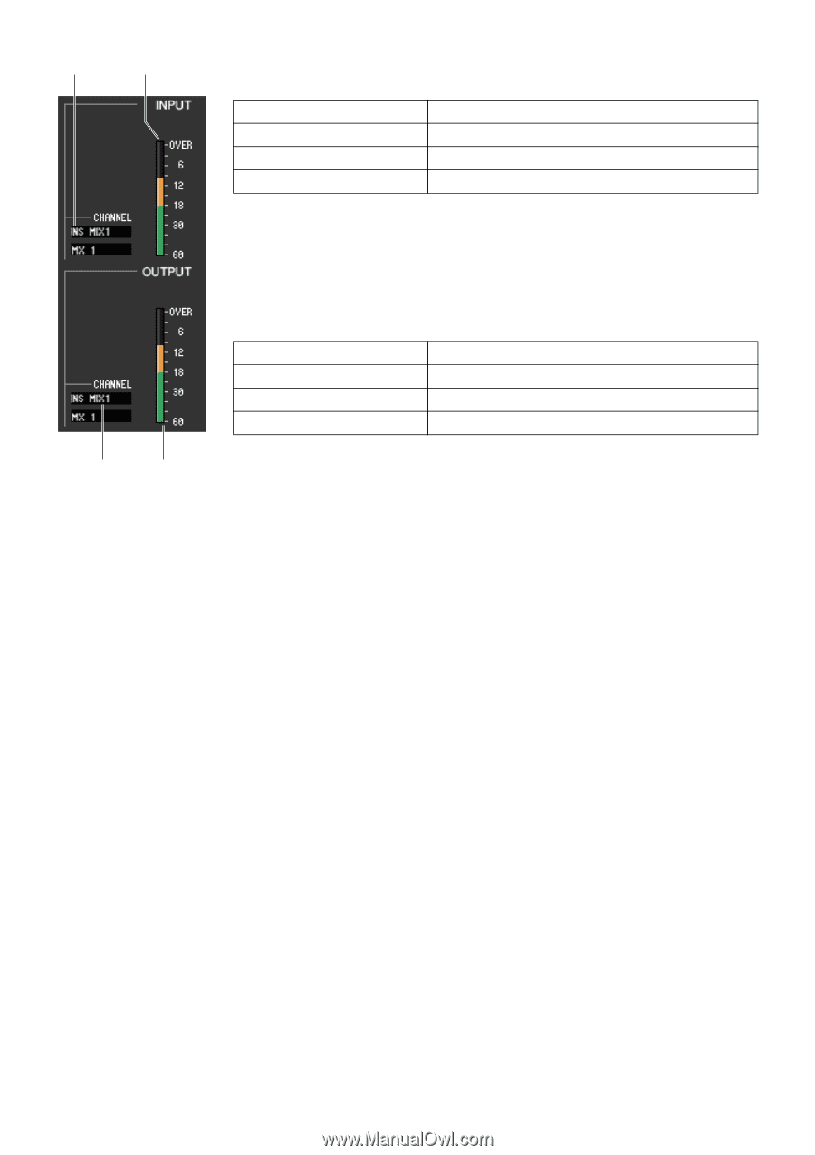
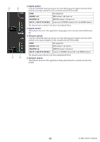
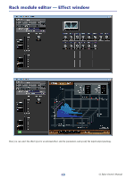
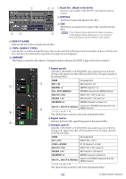
3 4 5 6 3 Input patch Click the CHANNEL field, and choose one of the following as the signal route that will be patched to the input channel(s) of the currently selected GEQ module. NONE No assignment INS MIX 1-24 MIX channel 1-24 insert out INS MTRX1-8 MATRIX channel 1-8 insert out INS ST L, INS ST R, INS M(C) Insert-out of STEREO channel L/R or the MONO channel The channel name is shown in the boxes immediately below. 4 Input meter This indicates the level of the signal that is being input to the currently selected GEQ module. 5 Output patch Click the CHANNEL field, and choose one of the following as the signal route that will be patched to the output channel(s) of the currently selected GEQ module. NONE No assignment INS MIX 1-24 MIX channel 1-24 insert in INS MTRX1-8 MATRIX channel 1-8 insert in INS ST L, INS ST R, INS M(C) Insert-in of STEREO channel L/R or the MONO channel The channel name is shown in the boxes immediately below. 6 Output meter This indicates the level of the signal that is being output from the currently selected GEQ module. 56 CL Editor Owner's Manual
-
 1
1 -
2
-
3
-
4
-
5
-
6
-
7
-
8
-
9
-
10
-
11
-
12
-
13
-
14
-
15
-
16
-
17
-
18
-
19
-
20
-
21
-
22
-
23
-
24
-
25
-
26
-
27
-
28
-
29
-
30
-
31
-
32
-
33
-
34
-
35
-
36
-
37
-
38
-
39
-
40
-
41
-
42
-
43
-
44
-
45
-
46
-
47
-
48
-
49
-
50
-
 51
51 -
 52
52 -
 53
53 -
 54
54 -
 55
55 -
 56
56 -
 57
57 -
 58
58 -
 59
59 -
 60
60 -
 61
61 -
62
-
63
-
64
-
65
-
66
-
67
-
68
-
69
-
70
-
71
-
72
-
73
-
74
-
75
-
76
-
77
-
78
-
79
-
80
-
81
-
82
-
83
-
84
-
85
-
86
-
87
-
88
-
89
 |
 |