Yamaha CL3 Cl Editor Owner's Manual - Page 61
Rack No. Rack selection, BYPASS, EFFECT NAME, TYPE EFFECT TYPE, LIBRARY, Input patch, Input meter
 |
View all Yamaha CL3 manuals
Add to My Manuals
Save this manual to your list of manuals |
Page 61 highlights
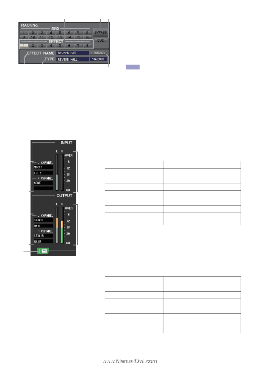
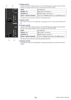
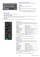
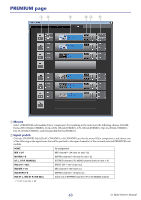
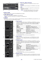
1 2 3 1 Rack No. (Rack selection) Select the rack module of the EFFECT rack that you want to control. 2 BYPASS This button temporarily bypasses the effect. 45 3 CUE This button cue-monitors the output of the currently selected effect. 6 NOTE If the Channel Select/Sends On Fader checkbox in the System Setup dialog box is not checked, the [CUE] button will be hidden in the screen. 4 EFFECT NAME Indicates the title of the currently selected effect. 5 TYPE (EFFECT TYPE) Indicates the currently selected effect type. You can also switch the effect type from this window. To do so, click the text box, and select the desired effect type from the popup menu that appears. 6 LIBRARY This button accesses the effect library. Clicking this button will open the EFFECT page of the Library window. 7 Input patch Click the L CHANNEL or R CHANNEL area, and choose one of the following as the signal route that will be patched to the L/R input channels of the internal effect. NONE No assignment 8 MIX 1-24 MIX channel 1-24 7 MATRIX1-8 MATRIX channel 1-8 ST L, ST R, MONO(C) STEREO channel L/R, MONO channel INS CH 1-72(*) INPUT CH 1-72(*) insert out INS MIX 1-24 MIX channel 1-24 insert out INS MTRX1-8 MATRIX channel 1-8 insert out 0 INS ST L, INS ST R, INS M(C) Insert-out of STEREO channel L/R or the MONO channel 9 (*) CL3: 1-64, CL1: 1-48 The channel name is shown in the boxes immediately below. 8 Input meter A Indicates the level of the signal being input to the internal effect. 9 Output patch Click the L CHANNEL or R CHANNEL area, and choose one of the fol- lowing as the signal route that will be patched to the L/R output channels of the internal effect. NONE No assignment CH 1-72(*) INPUT CH 1-72(*) STIN1L-STIN8R ST IN channel 1-8 (L/R) INS CH 1-72(*) INPUT CH 1-72(*) insert in INS MIX 1-24 MIX channel 1-24 insert in INS MTRX1-8 MATRIX channel 1-8 insert in INS ST L, INS ST R, INS M(C) Insert-in of STEREO channel L/R or the MONO channel (*) CL3: 1-64, CL1: 1-48 The channel name is shown in the boxes immediately below. 61 CL Editor Owner's Manual
-
 1
1 -
2
-
3
-
4
-
5
-
6
-
7
-
8
-
9
-
10
-
11
-
12
-
13
-
14
-
15
-
16
-
17
-
18
-
19
-
20
-
21
-
22
-
23
-
24
-
25
-
26
-
27
-
28
-
29
-
30
-
31
-
32
-
33
-
34
-
35
-
36
-
37
-
38
-
39
-
40
-
41
-
42
-
43
-
44
-
45
-
46
-
47
-
48
-
49
-
50
-
51
-
52
-
53
-
54
-
55
-
 56
56 -
 57
57 -
 58
58 -
 59
59 -
 60
60 -
 61
61 -
 62
62 -
 63
63 -
 64
64 -
 65
65 -
 66
66 -
67
-
68
-
69
-
70
-
71
-
72
-
73
-
74
-
75
-
76
-
77
-
78
-
79
-
80
-
81
-
82
-
83
-
84
-
85
-
86
-
87
-
88
-
89
 |
 |