Yamaha CL3 Cl Editor Owner's Manual - Page 36
Dca Group/mute Group, Fader, Dca Group, Mute Group, Dca/mute
 |
View all Yamaha CL3 manuals
Add to My Manuals
Save this manual to your list of manuals |
Page 36 highlights
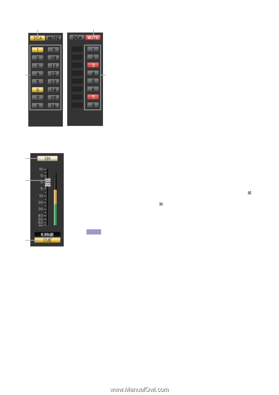
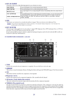
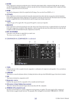
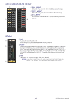
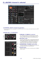
❏ DCA GROUP/MUTE GROUP 3 1 3 1 DCA GROUP Selects the DCA group (1-16) to which that channel belongs. 2 MUTE GROUP Selects the mute group (1-8) to which that channel belongs. 3 DCA/MUTE These buttons enable/disable DCA group and Mute group for the channel. 2 ❏ Fader 1 2 3 1 ON Switches the input channel on/off. If the corresponding channel is off, the fader will be grayed out. 2 Fader Adjusts the input level of the input channel. A meter indicating the signal level is shown at the right of the fader, and the current value is shown in the numerical box immediately below. You can set this to the minimum value (-∞ dB) by holding down the (< >) key of your computer keyboard and clicking the fader knob, or set it to the nominal value (0.00 dB) by holding down the (< >) key and key and clicking the fader knob. 3 CUE This button cue-monitors the signal of the input channel. NOTE If the Channel Select/Sends On Fader checkbox in the System Setup dialog box is not checked, the [CUE] button will be hidden in the screen. 36 CL Editor Owner's Manual
-
 1
1 -
2
-
3
-
4
-
5
-
6
-
7
-
8
-
9
-
10
-
11
-
12
-
13
-
14
-
15
-
16
-
17
-
18
-
19
-
20
-
21
-
22
-
23
-
24
-
25
-
26
-
27
-
28
-
29
-
30
-
 31
31 -
 32
32 -
 33
33 -
 34
34 -
 35
35 -
 36
36 -
 37
37 -
 38
38 -
 39
39 -
 40
40 -
 41
41 -
42
-
43
-
44
-
45
-
46
-
47
-
48
-
49
-
50
-
51
-
52
-
53
-
54
-
55
-
56
-
57
-
58
-
59
-
60
-
61
-
62
-
63
-
64
-
65
-
66
-
67
-
68
-
69
-
70
-
71
-
72
-
73
-
74
-
75
-
76
-
77
-
78
-
79
-
80
-
81
-
82
-
83
-
84
-
85
-
86
-
87
-
88
-
89
 |
 |