Yamaha CL3 Cl Editor Owner's Manual - Page 67
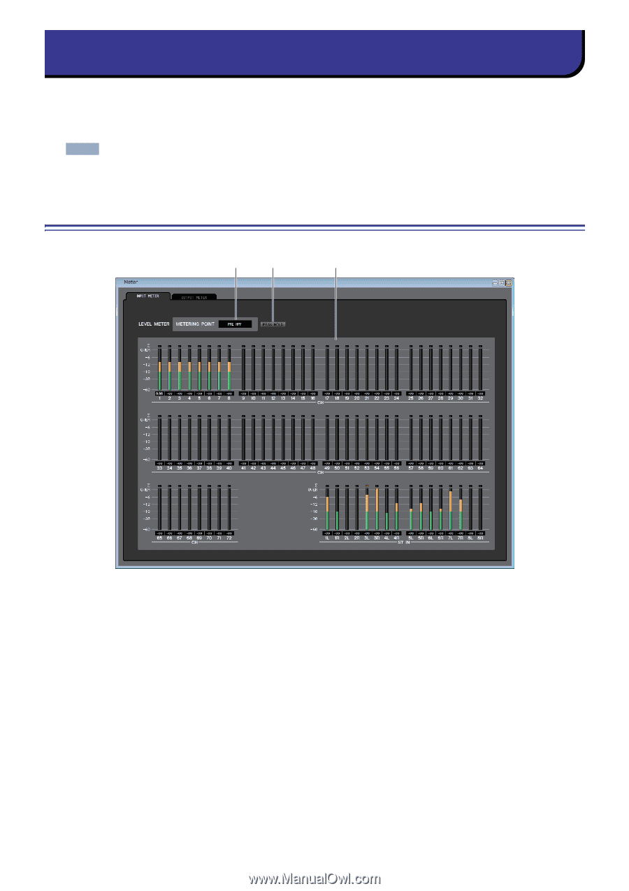
Meter window, INPUT METER
 |
View all Yamaha CL3 manuals
Add to My Manuals
Save this manual to your list of manuals |
Page 67 highlights
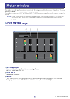
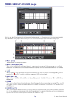
Meter window This window shows the signal levels of each section in the CL, letting you check for the presence of signals and whether an overload is occurring. This window is divided into INPUT METER and OUTPUT METER; to switch pages, click the tabs located at the top of the window. NOTE In order to view the CL's signal levels in the Meter window, make sure that CL Editor and the CL itself are synchronized. Also, please make sure that the Level Meter is enabled in the System Setup dialogbox ( ➥ p.2.) INPUT METER page 12 3 1 METERING POINT Select one of the following as the point where metering will occur. PRE HPF, PRE FADER, POST ON 2 PEAK HOLD Switches peak hold on/off. 3 Meters These peak level meters show the input level of each channel. The current fader value is shown in the box below. If clipping occurs at any one of the detection points in the channel, the segment will light. 67 CL Editor Owner's Manual
-
 1
1 -
2
-
3
-
4
-
5
-
6
-
7
-
8
-
9
-
10
-
11
-
12
-
13
-
14
-
15
-
16
-
17
-
18
-
19
-
20
-
21
-
22
-
23
-
24
-
25
-
26
-
27
-
28
-
29
-
30
-
31
-
32
-
33
-
34
-
35
-
36
-
37
-
38
-
39
-
40
-
41
-
42
-
43
-
44
-
45
-
46
-
47
-
48
-
49
-
50
-
51
-
52
-
53
-
54
-
55
-
56
-
57
-
58
-
59
-
60
-
61
-
 62
62 -
 63
63 -
 64
64 -
 65
65 -
 66
66 -
 67
67 -
 68
68 -
 69
69 -
 70
70 -
 71
71 -
 72
72 -
73
-
74
-
75
-
76
-
77
-
78
-
79
-
80
-
81
-
82
-
83
-
84
-
85
-
86
-
87
-
88
-
89
 |
 |