Yamaha CLP-535 Owner's Manual - Page 108
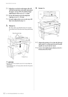
Mount A., Attach A., equally as seen from the rear.
 |
View all Yamaha CLP-535 manuals
Add to My Manuals
Save this manual to your list of manuals |
Page 108 highlights
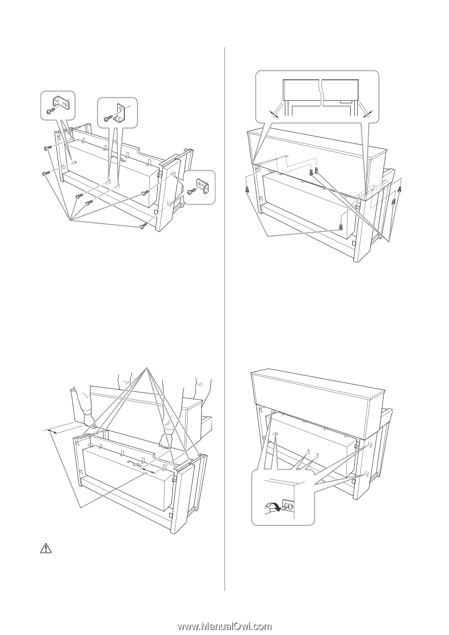
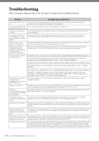
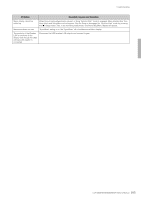
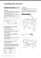
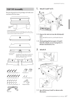
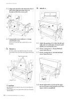
Assembling the Clavinova 2-2. Align and attach B to the front side of D, E and F, then align the larger holes on brackets of B to the screws on D. 4. Attach A. 4-1 B A 2-3 2-3. Temporarily secure with six 4 × 14 mm round head screws. Insert six screws into the smaller holes on the brackets. 3. Mount A. Be sure to place your hands at least 15 cm away from either end of the main unit when positioning it. Align the screw holes. 4-2 4-3 4-1. Adjust the position of A so that the left and right ends of A will project beyond E and F equally (as seen from the rear). 4-2. Secure A using two 6 × 20 mm flat head screws from the rear. 4-3. Secure A using four 6 × 20 mm flat head screws from the front. A F At least 15 cm 4-4 E CAUTION • Be extra careful not to drop the main unit or let your fingers be pinched by it. • Do not hold the main unit in any position other than the position specified above. 4-4. Firmly tighten the screws from the upper parts you temporarily fastened in previous step 2-3 above (assembly B). 108 CLP-585/575/545/535/565GP Owner's Manual
-
 1
1 -
2
-
3
-
4
-
5
-
6
-
7
-
8
-
9
-
10
-
11
-
12
-
13
-
14
-
15
-
16
-
17
-
18
-
19
-
20
-
21
-
22
-
23
-
24
-
25
-
26
-
27
-
28
-
29
-
30
-
31
-
32
-
33
-
34
-
35
-
36
-
37
-
38
-
39
-
40
-
41
-
42
-
43
-
44
-
45
-
46
-
47
-
48
-
49
-
50
-
51
-
52
-
53
-
54
-
55
-
56
-
57
-
58
-
59
-
60
-
61
-
62
-
63
-
64
-
65
-
66
-
67
-
68
-
69
-
70
-
71
-
72
-
73
-
74
-
75
-
76
-
77
-
78
-
79
-
80
-
81
-
82
-
83
-
84
-
85
-
86
-
87
-
88
-
89
-
90
-
91
-
92
-
93
-
94
-
95
-
96
-
97
-
98
-
99
-
100
-
101
-
102
-
 103
103 -
 104
104 -
 105
105 -
 106
106 -
 107
107 -
 108
108 -
 109
109 -
 110
110 -
 111
111 -
 112
112 -
 113
113 -
114
-
115
-
116
-
117
-
118
-
119
-
120
-
121
-
122
-
123
-
124
-
125
-
126
 |
 |