Brother International HL 2700CN Users Manual - English - Page 125
Push the lock levers down to lock the transfer roller into place.
 |
UPC - 840356824994
View all Brother International HL 2700CN manuals
Add to My Manuals
Save this manual to your list of manuals |
Page 125 highlights
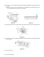
Figure 5-27 5) Put in the new transfer roller by holding the lock levers of the transfer roller and adjusting the angle of the transfer roller lever shafts (both sides) to match the transfer unit grooves. Put the transfer roller onto the shafts and place the roller onto the springs as shown below: Lock levers Transfer roller shaft Figure 5-28 Spring Figure 5-29 Figure 5-30 6) Push the lock levers down to lock the transfer roller into place. 7) Close the back cover. 8) Turn the printer power switch back on. 5 - 20 ROUTINE MAINTENANCE
-
 1
1 -
2
-
3
-
4
-
5
-
6
-
7
-
8
-
9
-
10
-
11
-
12
-
13
-
14
-
15
-
16
-
17
-
18
-
19
-
20
-
21
-
22
-
23
-
24
-
25
-
26
-
27
-
28
-
29
-
30
-
31
-
32
-
33
-
34
-
35
-
36
-
37
-
38
-
39
-
40
-
41
-
42
-
43
-
44
-
45
-
46
-
47
-
48
-
49
-
50
-
51
-
52
-
53
-
54
-
55
-
56
-
57
-
58
-
59
-
60
-
61
-
62
-
63
-
64
-
65
-
66
-
67
-
68
-
69
-
70
-
71
-
72
-
73
-
74
-
75
-
76
-
77
-
78
-
79
-
80
-
81
-
82
-
83
-
84
-
85
-
86
-
87
-
88
-
89
-
90
-
91
-
92
-
93
-
94
-
95
-
96
-
97
-
98
-
99
-
100
-
101
-
102
-
103
-
104
-
105
-
106
-
107
-
108
-
109
-
110
-
111
-
112
-
113
-
114
-
115
-
116
-
117
-
118
-
119
-
 120
120 -
 121
121 -
 122
122 -
 123
123 -
 124
124 -
 125
125 -
 126
126 -
 127
127 -
 128
128 -
 129
129 -
 130
130 -
131
-
132
-
133
-
134
-
135
-
136
-
137
-
138
-
139
-
140
-
141
-
142
-
143
-
144
-
145
-
146
-
147
-
148
-
149
-
150
-
151
-
152
-
153
-
154
-
155
-
156
-
157
-
158
-
159
-
160
-
161
-
162
 |
 |

5 - 20
ROUTINE MAINTENANCE
Figure 5-27
5)
Put in the new transfer roller by holding the lock levers of the transfer roller and adjusting the
angle of the transfer roller lever shafts (both sides) to match the transfer unit grooves. Put the
transfer roller onto the shafts and place the roller onto the springs as shown below:
Figure 5-28
6)
Push the lock levers down to lock the transfer roller into place.
7)
Close the back cover.
8)
Turn the printer power switch back on.
Figure 5-29
Figure 5-30
Lock levers
Transfer roller shaft
Spring