Canon LV-8225 LV-7290 User's Manual - Page 11
Rear Terminal, COMPUTER IN 2 / MONITOR OUT
 |
View all Canon LV-8225 manuals
Add to My Manuals
Save this manual to your list of manuals |
Page 11 highlights
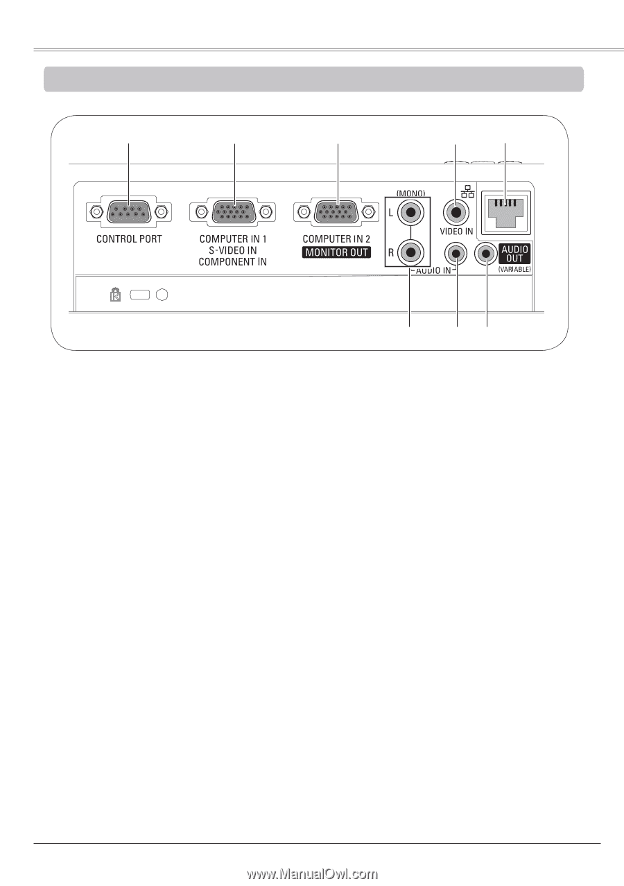
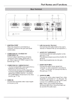
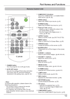
Part Names and Functions Rear Terminal ① ② ③ ④⑤ (MIC)- ⑧ᶉ ⑦⑥ ① CONTROL PORT When the projector is controlled by a computer, connect to this jack with serial control cable. ② COMPUTER IN 1 /S-VIDEO IN / COMPONENT IN Connect output signal from a computer, component video output, RGB scart 21pin video output or S-VIDEO output to this terminal (pp.17-19). ③ COMPUTER IN 2 / MONITOR OUT - Connect analog RGB output signal from a computer to this terminal (p.17). - This terminal can be used to output the incoming analog RGB and COMPONENT signal from COMPUTER IN 1 /S-VIDEO IN /COMPONENT IN terminal to the other monitor (pp.17,19). ④ VIDEO IN Connect the composite video output signal to this jack (p.18). ⑤ LAN Connection Terminal Connect the LAN cable (refer to the user's manual of "Network Set-up and Operation"). ⑥ AUDIO OUT (VARIABLE) Connect an external audio amplifier to this jack (pp.17-19). This terminal outputs sound from AUDIO IN terminal. Never plug headphones into this jack. ⑦ AUDIO IN (PC/MIC) Connect the audio output signal from computer or video equipment connected to ② and ③ to this jack. Or connect the MIC to this jack (pp.17-19). ⑧ AUDIO IN (L��/R��) Connect the audio output signal from video equipment connected to ④ to this jack. For a mono audio signal (a single audio jack), connect it to L(MONO) jack (p.18). Note: When using AUDIO IN(PC/MIC) terminal as MIC input, these terminals can be used for PC audio input. 11
-
 1
1 -
2
-
3
-
4
-
5
-
 6
6 -
 7
7 -
 8
8 -
 9
9 -
 10
10 -
 11
11 -
 12
12 -
 13
13 -
 14
14 -
 15
15 -
 16
16 -
17
-
18
-
19
-
20
-
21
-
22
-
23
-
24
-
25
-
26
-
27
-
28
-
29
-
30
-
31
-
32
-
33
-
34
-
35
-
36
-
37
-
38
-
39
-
40
-
41
-
42
-
43
-
44
-
45
-
46
-
47
-
48
-
49
-
50
-
51
-
52
-
53
-
54
-
55
-
56
-
57
-
58
-
59
-
60
-
61
-
62
-
63
-
64
-
65
-
66
-
67
-
68
-
69
-
70
-
71
-
72
-
73
-
74
-
75
-
76
-
77
-
78
-
79
-
80
-
81
-
82
-
83
 |
 |