Canon VB-S800D Mark II Network Camera Operation Guide - Page 183
Configuring Detection Criteria ([Detection Conditions] Tab), Click [Apply].
 |
View all Canon VB-S800D Mark II manuals
Add to My Manuals
Save this manual to your list of manuals |
Page 183 highlights
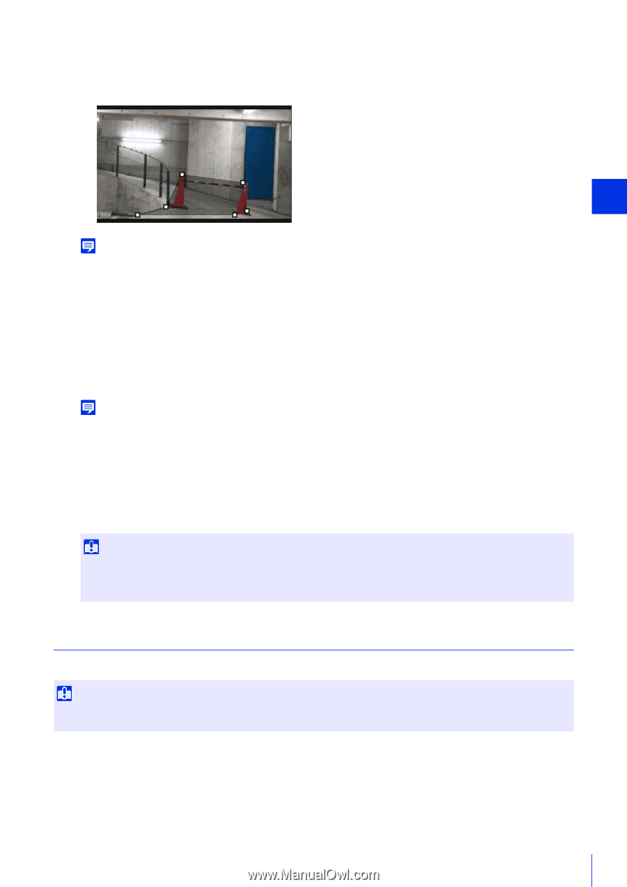
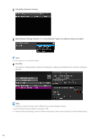
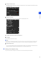
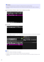
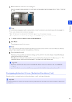
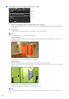
3 Set a non-detection area in the video display area. Click the mouse to create a polygon. For information on the creation method, please refer to "Using [Polygonal]" (P. 166). Note • You can create a polygonal area with a maximum of 32 vertices. You cannot set a non-detection area with only a straight line. • Click [Clear Area] to set the non-detection area again. • Enter [Non-detection Area Name (within 64 half-width alphanumeric characters)] as necessary. • The non-detection area is shown in the video display area in black. The display color cannot be selected. 4 To register multiple non-detection areas, repeat steps 2 and 3. 5 Click [Apply]. The settings are saved in the camera. Note Click [Clear] to discard the settings and restore the settings saved in the camera. However, note that non-detection areas only added to the non-detection areas by clicking [Add] are all discarded. 6 Check the detection result. The status of the specified non-detection settings can be checked in the video display area and the [Status] column in [Non-Detection Settings]. If the [Enable non-detection area] checkbox is cleared, [Disable] is displayed for the [Status] column in [NonDetection Settings], and the non-detection area is not shown in the video display area. Important • Make sure to check the video display area to see whether the detection area and non-detection area are unintentionally overlapped. • If you set the detection area and non-detection area close to each other, detection may be performed incorrectly. Configuring Detection Criteria ([Detection Conditions] Tab) Detection criteria is controlled and set in the video display area for each type of detection. Important It is recommended that you configure the detection criteria in conditions as close as possible to the actual conditions in which you will use the camera. Setting Page 5 165
-
 1
1 -
2
-
3
-
4
-
5
-
6
-
7
-
8
-
9
-
10
-
11
-
12
-
13
-
14
-
15
-
16
-
17
-
18
-
19
-
20
-
21
-
22
-
23
-
24
-
25
-
26
-
27
-
28
-
29
-
30
-
31
-
32
-
33
-
34
-
35
-
36
-
37
-
38
-
39
-
40
-
41
-
42
-
43
-
44
-
45
-
46
-
47
-
48
-
49
-
50
-
51
-
52
-
53
-
54
-
55
-
56
-
57
-
58
-
59
-
60
-
61
-
62
-
63
-
64
-
65
-
66
-
67
-
68
-
69
-
70
-
71
-
72
-
73
-
74
-
75
-
76
-
77
-
78
-
79
-
80
-
81
-
82
-
83
-
84
-
85
-
86
-
87
-
88
-
89
-
90
-
91
-
92
-
93
-
94
-
95
-
96
-
97
-
98
-
99
-
100
-
101
-
102
-
103
-
104
-
105
-
106
-
107
-
108
-
109
-
110
-
111
-
112
-
113
-
114
-
115
-
116
-
117
-
118
-
119
-
120
-
121
-
122
-
123
-
124
-
125
-
126
-
127
-
128
-
129
-
130
-
131
-
132
-
133
-
134
-
135
-
136
-
137
-
138
-
139
-
140
-
141
-
142
-
143
-
144
-
145
-
146
-
147
-
148
-
149
-
150
-
151
-
152
-
153
-
154
-
155
-
156
-
157
-
158
-
159
-
160
-
161
-
162
-
163
-
164
-
165
-
166
-
167
-
168
-
169
-
170
-
171
-
172
-
173
-
174
-
175
-
176
-
177
-
 178
178 -
 179
179 -
 180
180 -
 181
181 -
 182
182 -
 183
183 -
 184
184 -
 185
185 -
 186
186 -
 187
187 -
 188
188 -
189
-
190
-
191
-
192
-
193
-
194
-
195
-
196
-
197
-
198
-
199
-
200
-
201
-
202
-
203
-
204
-
205
-
206
-
207
-
208
-
209
-
210
-
211
-
212
-
213
-
214
-
215
-
216
-
217
-
218
-
219
-
220
-
221
-
222
-
223
-
224
-
225
-
226
-
227
-
228
-
229
-
230
-
231
-
232
-
233
-
234
-
235
-
236
-
237
-
238
-
239
-
240
-
241
-
242
-
243
-
244
-
245
-
246
-
247
-
248
-
249
-
250
-
251
-
252
-
253
-
254
-
255
-
256
-
257
-
258
-
259
-
260
 |
 |