Cisco 2948G Hardware Installation Guide - Page 108
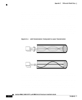
C-1, LED Transmission Compared to Laser Transmission
 |
UPC - 746320228884
View all Cisco 2948G manuals
Add to My Manuals
Save this manual to your list of manuals |
Page 108 highlights
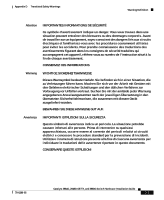
Appendix C Differential Mode Delay DMD does not occur in all deployed fibers; rather, it occurs with certain combinations of worst-case fibers and worst-case transceivers. Gigabit Ethernet is the first technology to experience this problem because of its very high baud rate and its long MMF cable lengths. SMF cable and copper cable are not affected by DMD. MMF cable has been tested for use only with LED sources. LEDs create a condition within a fiber-optic cable referred to as an overfilled launch condition. The overfilled launch condition describes the way LED transmitters couple light into the fiber-optic cable in a broad spread of modes. Similar to a light bulb radiating light in a dark room, the generated light that shines in multiple directions can overfill the existing cable space and excite a large number of modes. (See Figure C-1.) Figure C-1 LED Transmission Compared to Laser Transmission LED transmission LED Laser Laser transmission 12871 Lasers launch light in a more concentrated fashion. A laser transmitter couples light into only a fraction of the existing modes or optical pathways present in the fiber-optic cable. (See Figure C-1.) The solution to DMD in this case is to condition the laser light launched from the source (transmitter) so that it spreads the light evenly across the diameter of the fiber-optic cable, making the launch look more like an LED source to the cable. The objective is to scramble the modes of light to distribute the power more equally in all modes and prevent the light from being concentrated in just a few Catalyst 2984G, 2948G-GE-TX, and 2980G Switch Hardware Installation Guide C-2 78-6286-05
-
 1
1 -
2
-
3
-
4
-
5
-
6
-
7
-
8
-
9
-
10
-
11
-
12
-
13
-
14
-
15
-
16
-
17
-
18
-
19
-
20
-
21
-
22
-
23
-
24
-
25
-
26
-
27
-
28
-
29
-
30
-
31
-
32
-
33
-
34
-
35
-
36
-
37
-
38
-
39
-
40
-
41
-
42
-
43
-
44
-
45
-
46
-
47
-
48
-
49
-
50
-
51
-
52
-
53
-
54
-
55
-
56
-
57
-
58
-
59
-
60
-
61
-
62
-
63
-
64
-
65
-
66
-
67
-
68
-
69
-
70
-
71
-
72
-
73
-
74
-
75
-
76
-
77
-
78
-
79
-
80
-
81
-
82
-
83
-
84
-
85
-
86
-
87
-
88
-
89
-
90
-
91
-
92
-
93
-
94
-
95
-
96
-
97
-
98
-
99
-
100
-
101
-
102
-
 103
103 -
 104
104 -
 105
105 -
 106
106 -
 107
107 -
 108
108 -
 109
109 -
 110
110 -
 111
111 -
 112
112 -
 113
113 -
114
-
115
-
116
-
117
-
118
-
119
-
120
-
121
-
122
-
123
-
124
-
125
-
126
-
127
-
128
-
129
-
130
-
131
-
132
-
133
-
134
-
135
-
136
-
137
-
138
-
139
-
140
-
141
-
142
 |
 |
