Cisco 2948G Hardware Installation Guide - Page 69
Mounting the Catalyst 2948G-GE-TX Switch on a Table or Shelf, Connecting Power to the Switches - ge tx commands
 |
UPC - 746320228884
View all Cisco 2948G manuals
Add to My Manuals
Save this manual to your list of manuals |
Page 69 highlights
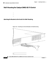
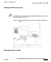
Chapter 3 Installing the Switch Connecting Power to the Switches Mounting the Catalyst 2948G-GE-TX Switch on a Table or Shelf To install the switch on a table or shelf, follow these steps: Step 1 Step 2 Step 3 Locate the adhesive strip with the rubber feet in the mounting-kit envelope. Attach the four rubber feet to the recessed areas on the bottom of the unit. Place the switch on the table or shelf near an AC power source. Connecting Power to the Switches To connect power to Catalyst 2948G, 2948G-GE-TX, and 2980G switches, follow these steps: Step 1 Step 2 Step 3 Step 4 Before you connect the power supply to a power source, ensure that all site power and grounding requirements described in "Site Planning" section on page 2-1 have been met. Plug the power cord into the chassis. Connect the other end of the power cord to an AC-power input source. Verify power supply operation by checking the front panel power supply LEDs: • When the power supply is operational, the LED is green. • When the power supply has failed, the LED is amber. From the system console, enter the show system command to display the power supply and system status. For more information on commands, refer to the command reference for your switch. 78-6286-05 Catalyst 2984G, 2948G-GE-TX, and 2980G Switch Hardware Installation Guide 3-19
-
 1
1 -
2
-
3
-
4
-
5
-
6
-
7
-
8
-
9
-
10
-
11
-
12
-
13
-
14
-
15
-
16
-
17
-
18
-
19
-
20
-
21
-
22
-
23
-
24
-
25
-
26
-
27
-
28
-
29
-
30
-
31
-
32
-
33
-
34
-
35
-
36
-
37
-
38
-
39
-
40
-
41
-
42
-
43
-
44
-
45
-
46
-
47
-
48
-
49
-
50
-
51
-
52
-
53
-
54
-
55
-
56
-
57
-
58
-
59
-
60
-
61
-
62
-
63
-
 64
64 -
 65
65 -
 66
66 -
 67
67 -
 68
68 -
 69
69 -
 70
70 -
 71
71 -
 72
72 -
 73
73 -
 74
74 -
75
-
76
-
77
-
78
-
79
-
80
-
81
-
82
-
83
-
84
-
85
-
86
-
87
-
88
-
89
-
90
-
91
-
92
-
93
-
94
-
95
-
96
-
97
-
98
-
99
-
100
-
101
-
102
-
103
-
104
-
105
-
106
-
107
-
108
-
109
-
110
-
111
-
112
-
113
-
114
-
115
-
116
-
117
-
118
-
119
-
120
-
121
-
122
-
123
-
124
-
125
-
126
-
127
-
128
-
129
-
130
-
131
-
132
-
133
-
134
-
135
-
136
-
137
-
138
-
139
-
140
-
141
-
142
 |
 |