Cisco 2948G Hardware Installation Guide - Page 73
Verifying Switch Operation
 |
UPC - 746320228884
View all Cisco 2948G manuals
Add to My Manuals
Save this manual to your list of manuals |
Page 73 highlights
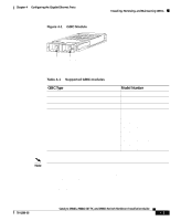
Chapter 3 Installing the Switch Verifying Switch Operation Figure 3-16 Ethernet Cable with RJ-45 Connector 98459 Verifying Switch Operation After you have connected all the interfaces, check all connections, and then perform the following steps to power on the system to verify that it is operational: Step 1 Step 2 Step 3 Step 4 Step 5 Step 6 Before powering on the system, make sure the connector is installed securely in a grounded outlet at the power-source end of the power cord and that the source power is within the range labeled on the back of the switch. When two power supplies are present, make sure that the second cord is connected to a separate line from the first, if possible. Check the console terminal and make sure it is powered on. Connect the power cords to the switch. Verify that the PSI or PWR LEDs on the power supply front panel is green. Listen for the system fans to ensure that they are operational. While the system initializes, check that the STATUS LED on the supervisor engine is amber until the boot is complete. Note Many of the interface LEDs do not illuminate until you configure the interfaces. When the system boot is complete (it takes a few seconds), the supervisor engine begins to initialize the interfaces. During this initialization, the interface LEDs flash on and off. When initialization is complete, the console screen displays a script and system banner. 78-6286-05 Catalyst 2984G, 2948G-GE-TX, and 2980G Switch Hardware Installation Guide 3-23
-
 1
1 -
2
-
3
-
4
-
5
-
6
-
7
-
8
-
9
-
10
-
11
-
12
-
13
-
14
-
15
-
16
-
17
-
18
-
19
-
20
-
21
-
22
-
23
-
24
-
25
-
26
-
27
-
28
-
29
-
30
-
31
-
32
-
33
-
34
-
35
-
36
-
37
-
38
-
39
-
40
-
41
-
42
-
43
-
44
-
45
-
46
-
47
-
48
-
49
-
50
-
51
-
52
-
53
-
54
-
55
-
56
-
57
-
58
-
59
-
60
-
61
-
62
-
63
-
64
-
65
-
66
-
67
-
 68
68 -
 69
69 -
 70
70 -
 71
71 -
 72
72 -
 73
73 -
 74
74 -
 75
75 -
 76
76 -
 77
77 -
 78
78 -
79
-
80
-
81
-
82
-
83
-
84
-
85
-
86
-
87
-
88
-
89
-
90
-
91
-
92
-
93
-
94
-
95
-
96
-
97
-
98
-
99
-
100
-
101
-
102
-
103
-
104
-
105
-
106
-
107
-
108
-
109
-
110
-
111
-
112
-
113
-
114
-
115
-
116
-
117
-
118
-
119
-
120
-
121
-
122
-
123
-
124
-
125
-
126
-
127
-
128
-
129
-
130
-
131
-
132
-
133
-
134
-
135
-
136
-
137
-
138
-
139
-
140
-
141
-
142
 |
 |
