Cisco 2948G Hardware Installation Guide - Page 39
Power Supplies - 48
 |
UPC - 746320228884
View all Cisco 2948G manuals
Add to My Manuals
Save this manual to your list of manuals |
Page 39 highlights
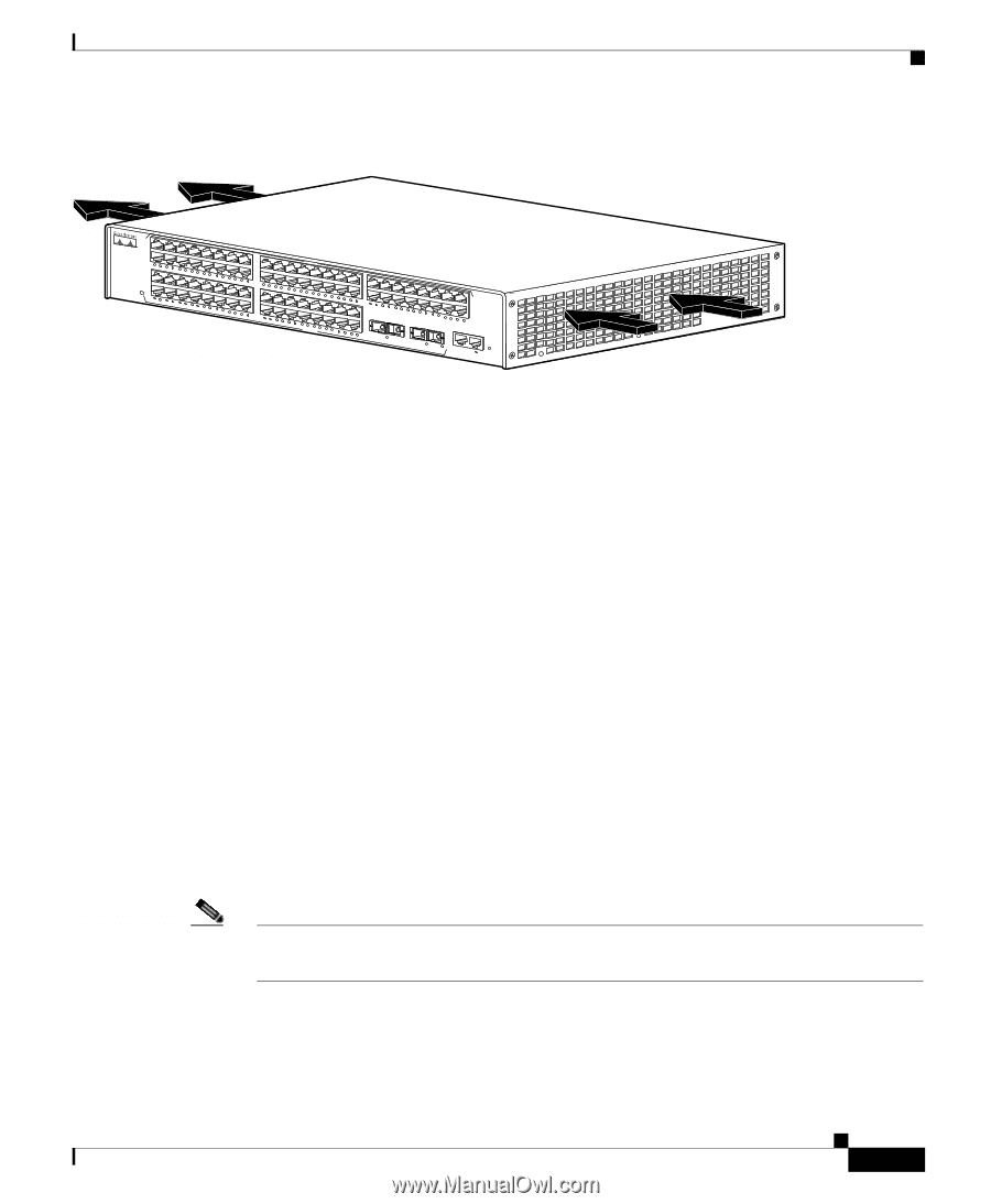
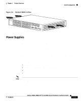
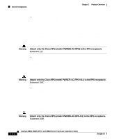
Chapter 1 Product Overview Figure 1-6 Catalyst 2980G Airflow Switch Components 32064 1 2 1 1 2 3 4 56 78 9 10 11 12 13 14 15 16 STATUS 10/100/1000 ETHERENET 2 1 2 3 4 5 6 7 8 9 10 11 12 13 14 15 16 SLOT 2 17 18 19 20 21 22 23 24 25 26 27 28 29 30 31 32 17 18 19 20 21 22 23 S2L4OT253 26 27 28 29 30 31 32 47 CATALYST 2986 33 31 34 35 36 37 38 39 40 41 42 43 44 45 46 47 48 48 32 33 CONSOLE 10MB MGT 34 PWR RESET Power Supplies There is no power switch on the switches. AC power is present in the power supply when the power cord is plugged in. The environmental monitoring and reporting functions allow you to maintain normal system operation by correcting adverse environmental conditions before loss of operation. Each power supply monitors its own temperature and output voltages. If the power supply becomes excessively hot, it shuts down to prevent damage. The switches monitor the operating condition of the power supply and report the status using switch software. The switches have the following power supplies: • 120 W AC internal power supply-Catalyst 2948G switch • 156 W AC internal power supply-Catalyst 2948G-GE-TX switch • 175 W AC internal power supply-Catalyst 2980G switch • 156 W AC internal power supply-Catalyst 2980G-A switch Note For complete power specifications for the Catalyst 2948G, 2948G-GE-TX, and 2980G switches, see Appendix A, "Specifications." These switches also be used with an optional Cisco Redundant Power System (RPS). 78-6286-05 Catalyst 2984G, 2948G-GE-TX, and 2980G Switch Hardware Installation Guide 1-11
-
 1
1 -
2
-
3
-
4
-
5
-
6
-
7
-
8
-
9
-
10
-
11
-
12
-
13
-
14
-
15
-
16
-
17
-
18
-
19
-
20
-
21
-
22
-
23
-
24
-
25
-
26
-
27
-
28
-
29
-
30
-
31
-
32
-
33
-
 34
34 -
 35
35 -
 36
36 -
 37
37 -
 38
38 -
 39
39 -
 40
40 -
 41
41 -
 42
42 -
 43
43 -
 44
44 -
45
-
46
-
47
-
48
-
49
-
50
-
51
-
52
-
53
-
54
-
55
-
56
-
57
-
58
-
59
-
60
-
61
-
62
-
63
-
64
-
65
-
66
-
67
-
68
-
69
-
70
-
71
-
72
-
73
-
74
-
75
-
76
-
77
-
78
-
79
-
80
-
81
-
82
-
83
-
84
-
85
-
86
-
87
-
88
-
89
-
90
-
91
-
92
-
93
-
94
-
95
-
96
-
97
-
98
-
99
-
100
-
101
-
102
-
103
-
104
-
105
-
106
-
107
-
108
-
109
-
110
-
111
-
112
-
113
-
114
-
115
-
116
-
117
-
118
-
119
-
120
-
121
-
122
-
123
-
124
-
125
-
126
-
127
-
128
-
129
-
130
-
131
-
132
-
133
-
134
-
135
-
136
-
137
-
138
-
139
-
140
-
141
-
142
 |
 |